


DRICO
slife
FU 12
Operating Manual
_______________________________________________________________________________________________________________________________________
DIN EN ISO 9001
status: 31.03.2017 / Rev. 01
page 40 of 48
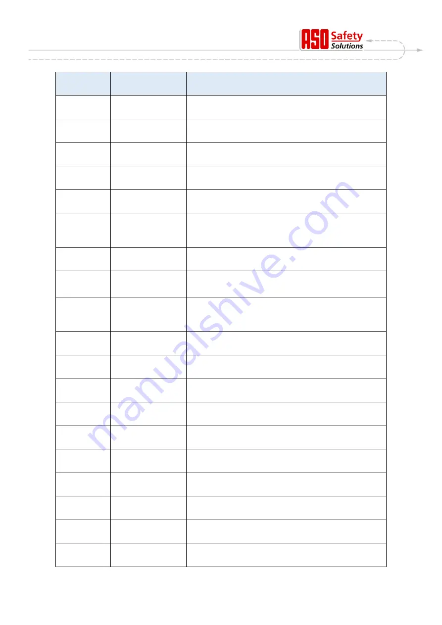
Reference-/
error no.
Text
Meaning
205
StackErr:high
The motor controller detected a memory stack error
(fatal exception error)
206
WdgErr:low
The motor controller detected watchdog error
(fatal exception error)
207
WdgErr:high
The motor controller detected watchdog error
(fatal exception error)
208
Watchdog error
The motor controller detected watchdog error
(fatal exception error)
209
WDG Reset
The motor controller was restarted by the watchdog
210
MotRunt.Err
Motor movement was stopped because the maximum
motor runtime for this gate movement was reached
(end switch was not reached in the max. time)
[Gate check required]
211
main-cntErr.
The motor controller‘s main loop counter was overrun
(fatal exception error)
212
Undef.Stat.
The variable for status automation reached an invalid
value
(fatal exception error)
213
LimitTimeErr.
The end switch was not left within the maximum permitted
time (4 sec.)
(Gate disengaged or very sluggish)
[Gate check required]
214
< Maintenance >
required
One of the specified maintenance events (gate cycles,
maintenance interval) has been reached
217
EEPR.Err.Txt
The desired display text was not found in the memory
218
EEPR.Err.Wr.
An error occurred while writing a text in the memory
219
EEPR.Err.Lang
An error with the pointer address occurred for a text in the
memory
220
MotorErr.
Motor movement was stopped due to a motor monitoring
signal
225
FC Fault Err
The frequency converter‘s power component detects a
high motor current
226
FC Temp.Err
The frequency converter module detects a high operating
temperature
228
REL+Err.High
The voltage monitoring for the release signal measured a
value that was too high
229
REL+Err.Low
The voltage monitoring for the release signal measured a
value that was too low
230
REL+Err.Idl
The voltage monitoring for the release signal measured a
value that was too high for the open-circuit voltage


