background image

20

309902

Pressure Control Repair

Motor Control Board Diagnostics

Note:

Keep a new transducer on hand to use for test.

CAUTION

Do not allow sprayer to develop fluid pressure with-

out transducer installed. Leave drain valve open if

test transducer is used.

1. Fig. 6 and 8. Remove four screws (23) and cover

(56).

2. Turn ON/OFF switch ON.
3. Observe LED operation and reference following

table:

Relieve pressure and unplug sprayer before

servicing control board; page 5.

LED

BLINKS

SPRAYER OPERATION

INDICATES

WHAT TO DO

Once

Sprayer runs

Normal operation

Do nothing

Once and

stays ON

Sprayer shuts down and LED stays ON

Motor open circuit or bad

control board

Check motor brushes and

armature. If OK, replace mo-

tor control board.

Two times

repeatedly

Sprayer shuts down and LED continues

to blink two times repeatedly

Run away pressure. Pres-

sure greater than 4500 psi

(310 bar, 31 MPa).

Replace motor control board.

See following

Motor Control

Board

procedure.

Three times

repeatedly

Sprayer shuts down and LED continues

to blink three times repeatedly

Pressure transducer is

faulty or missing

Check transducer connection.

Open drain valve. Substitute

new transducer for transducer

in sprayer. If sprayer runs,

replace transducer.

Four times

repeatedly

Sprayer shuts down and LED continues

to blink four times repeatedly

Line voltage is too high

Check for voltage supply

problems

Five times

repeatedly

Sprayer shuts down and LED continues

to blink five times repeatedly

Too much current

Check for locked rotor,

shorted wiring or motor. Re-

pair or replace failed parts.

Six times

repeatedly

Sprayer shuts down and LED continues

to blink six times repeatedly

Motor thermal switch

open circuit

Check for binding in pump or

drive. Check for bad motor.

Summary of Contents for 246796

Page 1: ... coatings Model 246796 Series A B and 249308 3000 psi 20 7 MPa 207 bar Maximum Working Pressure 309902F Manufactured by Important Safety Instructions Read all warnings and instructions in this manual Save these instructions ti3639b Related Manuals 309904 307806 Model 246796 Series A 311061 Model 246796 Series B Model 249308 ...

Page 2: ...ble liquid is used in or near sprayer or for flushing or cleaning keep sprayer at least 20 ft 6 m away from explosive vapors D Keep work area free of debris including solvent rags and gasoline D Do not plug or unplug power cords or turn lights on or off when flammable fumes are present D Ground equipment and conductive objects in work area Read Grounding instructions D If there is static sparking ...

Page 3: ...tigued or under the influence of drugs or alcohol D Comply with all applicable safety regulations PRESSURIZED ALUMINUM PARTS HAZARD Do not use 1 1 1 trichloroethane methylene chloride other halogenated hydrocarbon solvents or fluids containing such solvents in this equipment Such use could result in a serious chemical reaction with the possibility of explosion which could cause death serious injur...

Page 4: ...l Controls motor speed to maintain fluid outlet pressure at displacement pump outlet Works with pressure adjusting knob K ON OFF Switch Power switch that controls main power to sprayer M 50 ft 15 m Main Hose 1 4 in ID grounded nylon hose with spring guards on both ends N Spray Gun High pressure spray gun with gun safety latch P Spray Tip Uses high pressure fluid to clear tip clogs without removing...

Page 5: ...wire connectors properly Center flat blade of insulated male connector in female connector D Route wires carefully to avoid interference with other connections of pressure control Do not pinch wires between cover and control box 1 Keep all screws nuts washers gaskets and electrical fittings removed during repair proce dures These parts are not normally provided with replacement assemblies Read war...

Page 6: ... sprayer performance Grounding and Electric Requirements D Ground sprayer gun through connection to a properly grounded fluid hose and pump D Ground fluid supply container Follow local code D Ground solvent pails used when flush ing Follow local code Use only conduc tive metal pails placed on a grounded surface such as concrete Do not place the pail on a non conductive surface such as paper or car...

Page 7: ...to pail and the other end to ground such as a water pipe D Maintain grounding continuity when flushing or relieving pressure by hold ing metal part of spray gun firmly to side of a grounded metal pail then trigger gun Grounding and Electric Requirements ti5851a ti6762a ...

Page 8: ...rol knob setting 1 Motor stops running when pressure setting is reached 2 Pump 13 for frozen or hardened paint 2 Thaw sprayer if water or water based paint has frozen in sprayer Place sprayer in warm area to thaw Do not start sprayer un til thawed completely If paint hardened dried in sprayer replace pump packings Displacement Pump Replacement page 25 2 Displacement pump connecting rod pin 112 Pin...

Page 9: ... cleaning brush Align brush leads with slot in brush holder to assure free verti cal brush movement 10 Motor armature commutator for burn spots gouges and extreme roughness See page 14 10 Remove motor and have motor shop resur face commutator if possible page 24 11 Motor armature for shorts using armature tester growler or perform spin test See page 13 11 Replace motor page 24 Refer to wiring diag...

Page 10: ...to circuit board 100 for damaged or loose wires or connectors In spect wiring insulation and terminals for signs of overheating 8 Be sure male terminal blades are cen tered and firmly connected to female ter minals Replace any loose terminal or damaged wiring Securely reconnect ter minals 9 For loose motor brush leads and terminals page 14 9 Tighten terminal screws Replace brushes if leads are dam...

Page 11: ...uld clog pump 5 Leaking around throat packing nut which may indicate worn or damaged packings page 25 5 Replace packings page 25 Also check piston valve seat for hardened paint or nicks and replace if necessary Tighten packing nut wet cup 6 Pump rod damage 6 Repair pump page 25 7 Capacitor failure Visually inspect capacitor near terminals Ensure that orange safety relief plug is intact 7 Replace c...

Page 12: ...l shorts before 3 Motor armature for shorts Use an armature tester growler or perform spin test page 13 Inspect windings for burns 3 Replace motor page 24 and repair all shorts before checking and replacing control board 4 Pressure control board 100 by performing motor control board diagnostics page 20 If diagnostics indicate substitute with a good board CAUTION Do not perform this check until mot...

Page 13: ...lectrical shorts motor coasts two or three revolutions before complete stop If motor does not spin freely armature is shorted Replace motor page 24 Armature Brushes and Motor Wiring Open Circuit Test Continuity 1 Connect red and black motor leads together with test lead Turn motor fan by hand at about two revolutions per second 2 If uneven or no resistance check for broken brush springs brush lead...

Page 14: ... A and gaskets on each side of motor 3 Fig 4 Push in spring clip J to release hook B from brush holder C Pull out spring clip 4 Fig 4 Loosen terminal screw D Pull brush lead E out of terminal leaving motor lead F in place Remove brush G and spring H 5 Inspect commutator for excessive pitting burning or gouging A black color on commutator is normal Have commutator resurfaced by a motor repair shop ...

Page 15: ...r side 5 Test brushes a Remove pump connecting rod pin 112 refer to Removal step 5 page 25 b With sprayer OFF turn pressure control knob fully counterclockwise to minimum pressure Plug in sprayer c Turn sprayer ON Slowly increase pressure until motor is at full speed 6 Fig 3 Install gaskets and inspection covers A on each side of motor CAUTION To avoid damaging pump packing do not run sprayer dry ...

Page 16: ...rom ON OFF switch 86 3 Remove toggle boot 42 and locking ring 43 Remove ON OFF switch 86 Installation 1 Install new ON OFF switch 86 Install locking ring 43 and toggle boot 42 2 Connect two wires A to ON OFF switch Wiring diagrams 3 Install pressure control cover 56 with four screws 23 56 A 23 86 E D 100 38 42 43 20 26 E 124 68 36 32 32 133 64 70 ti2157d Fig 6 ...

Page 17: ...17 309902 Wiring Diagram Model 246796 Fig 7 102 60 75 64 68 66 86 45 ON OFF Switch Black white Red M M L2 L1 TO2 TO1 2X Yellow Black Green White TI3206B DETAIL B Black white Red 2X Yellow B ...

Page 18: ...4 Squeeze inside tabs on ON OFF switch 18 and remove from control panel 67 Installation 1 Push ON OFF switch 18 into control panel 67 until inside tabs snap in place 2 Connect two wires A to ON OFF switch 18 3 Install control panel 67 with two screws 108 4 Connect display connector B not available on all sprayers Install pressure control cover 56 with four screws 23 Fig 8 ti6836a 56 23 67 18 36 D ...

Page 19: ...19 309902 Wiring Diagram Model 249308 6489A Fig 9 ...

Page 20: ...LED continues to blink two times repeatedly Run away pressure Pres sure greater than 4500 psi 310 bar 31 MPa Replace motor control board See following Motor Control Board procedure Three times repeatedly Sprayer shuts down and LED continues to blink three times repeatedly Pressure transducer is faulty or missing Check transducer connection Open drain valve Substitute new transducer for transducer ...

Page 21: ...Lead D from potentiometer D Lead E from transducer 3 Remove five screws 38 and control board 100 Installation 1 Clean pad on rear of motor control board Apply small amount of thermal compound 073019 to pad 2 Install motor control board 100 with five screws 38 3 Connect to motor control board 100 D Lead E to transducer D Lead D to potentiometer D Two line voltage leads D Four motor leads two yellow...

Page 22: ... 124 3 Install filter housing 69 with three screws 98 Connect hose 65 4 Connect lead E to control board 100 5 Install cover 56 with four screws 23 Pressure Adjust Potentiometer Removal Refer to Fig 6 9 Relieve pressure page 5 1 Remove four screws 23 and cover 56 2 Disconnect all leads from control board 100 3 Remove five screws 38 and board 100 4 Remove potentiometer knob 36 sealing shaft nut 32 a...

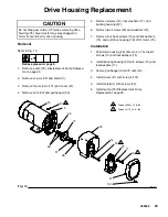
Page 23: ...9 lock washers 17 and bearing housing 67 6 Remove two screws 20 and washers 15 7 Remove four back screws 10 and lockwashers 15 and pull drive housing 78 off of motor 75 Installation 1 Push drive housing 78 onto motor 75 Install screws 10 and lockwashers 15 2 Install bearing housing 67 with screws 19 and lockwashers 17 3 Secure pail hanger 54 with nuts 33 4 Install cover 41 with screws 101 5 Instal...

Page 24: ... 38 and board 100 6 Remove strain relief 73 Refer to page 28 Thread motor leads out through hole in frame 7 Fig 11 Remove four screws 31 nuts 89 and motor 75 Assembly 1 Install new motor 75 on bracket 2 and frame with four screws 31 and nuts 89 2 Thread motor leads through hole in frame and into control box 70 3 Install strain relief 73 4 Fig 6 and 8 Install board 100 with five screws 38 Connect a...

Page 25: ...uring operation the threads of the bearing housing will be damaged Make sure locknut is properly tightened 1 Fig 15 Pull piston rod out 1 5 in Screw in pump until holes in connecting rod cross link and piston rod align Fig 15 1 5 in 2 Fig 13 Push pin 112 into hole And push retain ing spring 27 into groove all the way around connecting rod 3 Fig 16 Screw locknut down onto pump until nut stops Screw...

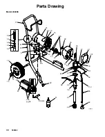
Page 26: ...wing DETAIL A A 6 10 15 12 14 16 17 19 20 31 22 REF 27 28 33 34 37 39 46 52 54 75 76 67 77 78 85 89 101 REF 112 41 REF 72 REF 71 106 24 25 72 15 129 28 TI3202d 71 95 82 97 79 49 65 55 27 112 44 113 Model 246796 see pg 28 ...

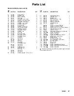
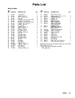
Page 27: ...ER pail 1 55 NUT hex 1 178941 series A 192723 series B 65 243994 HOSE coupled 1 4 in x 13 in 67 246709 HOUSING bearing 1 71 245245 HANDLE cart 1 72 196617 FRAME cart 1 75 246500 MOTOR electric 1 hp 1 76 241008 ROD connecting 1 77 244264 GEAR combination 1 78 246708 HOUSING drive 1 79 PUMP 1 222580 series A manual 307806 287161 series B manual 311061 80 277201 HOSE cpld 1 4 in x 50 ft not shown 1 8...

Page 28: ...28 309902 Parts Drawing Model 246796 TI3204A 18 132 57 69 98 30 51 58 26 68 29 50 62 63 REF 95 65 59 96 61 21 131 130 TI3205A 32 36 42 43 56 70 64 100 86 38 23 66 74 126 125 104 87 124 103 45 73 133 ...

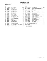
Page 29: ...PACKING o ring 1 62 235014 VALVE drain 1 63 224807 BASE valve 1 64 236352 POTENTIOMETER adjustment 1 65 243994 HOSE coupled 1 REF NO PART NO DESCRIPTION QTY 66 246447 CORD SET power 1 68 243222 TRANSDUCER pressure 1 69 15C140 HOUSING filter 1 70 15B961 BOX control 1 73 114689 BUSHING strain relief 1 74 195423 GROMMET transducer 1 86 111930 SWITCH toggle 1 87 117745 BUSHING strain relief 1 96 15C14...

Page 30: ...09902 Parts Drawing Model 249308 95 82 22 72 14 12 16 97 79 49 41 101 15 75 10 28 78 77 37 71 52 34 46 25 24 95 Ref 23 65 20 15 76 6 31 55 27 112 33 111 54 19 17 89 44 39 67 TI0867C 61 57 85 53 91 see pg 32 ...

Page 31: ...1 52 192027 SLEEVE cart 2 53 195805Y LABEL DANGER ST 1 54 192719 HANGER pail 1 55 192723 NUT retaining 1 57 115F329 LABEL crtl box cover 1 61 206994 FLUID tsl 8 oz bottle 1 65 243994 HOSE coupled 1 4 in x 13 in 1 67 246709 HOUSING bearing 1 71 239998 HANDLE cart 1 72 196617 FRAME cart 1 75 243723 MOTOR electric 1 76 241008 ROD connecting 1 77 244264 GEAR combination 1 includes 28 and 37 78 287829 ...

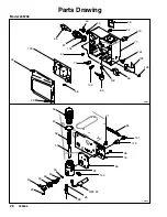
Page 32: ...2 309902 Parts Drawing Model 249308 ti6837a ti6837a 136 60 108 137 86 36 32 96 64 58 106 41 145 140 11 56 21 134 146 38 47 138 66 23 42 43 73 13 80 139 69 141 50 62 63 51 29 74 45 68 26 30 REF 95 REF 65 ...

Page 33: ...n 1 63 114708 SPRING compression 1 64 236352 POTENTIOMETER adjust pressure 1 66 196836 CORD power 1 REF NO PART NO DESCRIPTION QTY 68 243222 TRANSDUCER pressure contl 1 includes 26 69 196676 HOUSING filter 1 73 196675 BOWL filter 1 74 181740 CAP 1 80 243984 FILTER FLUID 60 mesh 1 86 116098 SWITCH power 1 96 116200 SPACER shaft 1 106 196707 GASKET control ULTRA 1 108 116304 SCREW mach pan hd 4 134 ...

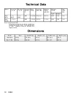
Page 34: ... 8 3 0 0 027 0 019 1 4 in Mach 11000 1 15 50 4000 1 2 560 200 53 1 1 3 8 0 031 0 021 1 4 in Basic Sprayer Wetted Parts zinc plated carbon steel polyurethane polyethylene stainless steel PTFE Acetal chrome plating leath er V Maxt UHMWPE aluminum stainless steel tungsten carbide Dimensions Model Style Weight lb kg Height in cm Width in cm Length in cm Mach 8600 Hi Boy 107 48 5 30 76 20 5 52 1 28 71 ...

Page 35: ...35 309902 Notes ...

Page 36: ...S OR IMPLIED INCLUDING BUT NOT LIMITED TO WARRANTY OF MERCHANTABILITY OR WARRANTY OF FITNESS FOR A PARTICULAR PURPOSE ASM s sole obligation and buyer s sole remedy for any breach of warranty shall be as set forth above The buyer agrees that no other remedy including but not limited to incidental or consequential damages for lost profits lost sales injury to person or property or any other incident...

Reviews: