4.10. Transmitted light polarization
ere are different variants of investigation for
filter pusher formed like an intermediate tube
.10.1. A
polarization filter
insertable in the
Th
polarization in transmitted light illumination
analogue to incident light illumination for the
analyser for the variants I and II.
A
includes two parallel-aligned polarization fil-
ters, which can be pushed to the left side in
the path of the light beam with the help of one
of the two knobs. The microscope must not be
refocused when observing with or without a
polarization filter. It is possible to insert com-
pensators for the determination of path differ-
ences on double-refracting materials or of rota-
tions of the polarization level. According to in-
tended use, a tipping or rotating compensator
inside the two guides on the right side of the
filter pusher can be inserted diagonally to one
of the polarizers.
4
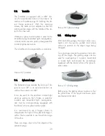
turntable serves as a polarizer. Screw this into
the turntable so that the markings on it agree
with those on the turntable. When using it in
combination with the filter pusher, align it to
the darkening while looking through the bin-
ocular tube and fasten it with both screws.
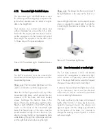
Picture 18: Turntable with Polarizer
.10.2. When using it in combination with
therefore be adjusted afterwards.
ki
let stimu-
tion is available for fluorescent investigations.
The e
xcitation filters
in the
lug-in socket can be exchanged. To do this,
lter
usher formed like an intermediate tube. The
4
the filter pusher, align it to the darkening while
looking through the binocular tube and fasten it
with both screws. Alignment is meaningless
when using the analyser set in front of the ob-
jective, since the analyser is rotatable and can
4.11. Incident Light Fluorescence
A filter t for blue, green and blue-vio
la
Fluorescent stimulation results via one of the
plug-in stimulation filters in front of the collector
of the 6V/20W illuminator or the 3W-LED il-
luminator.
4.11.1.
p
press out the filter combination with a non-
fuzzy cloth and lay the desired stimulation filter
combination into the socket. Set in the binding
ring and carefully press against the filter.
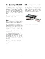
4.11.2. The
blocking filters
are in a fi
p
tube will be assembled between the middle
part of the microscope and the binocular tube.
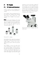
Picture 19: Fluorescence device
in the path of
e light beam with the aid of one of the two
.11.3.
When using a
cold light de-
ice
you can set the corresponding stimulation
Attach the filters to the left side
th
push knobs. If you need other fluorescent
blocking filters other than those supplied with
the standard equipment, they can be traded
before the assembly of the filter pusher. This
can be only done in the factory.
4
v
filters directly in front of the light guide outlet
by unscrewing the focusing adapter. The right
blocking filter has to be done again into the
filter pusher.
20


