4.12. Transmitted light -Dark-field device
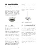
The transmitted light – dark field device is used
r
b-
cts whose structures are not easily recogniz-
nly visible in the dark-
eld. After the object plate has been removed,
for obse ving and investigating transparent o
je
able in the brightfield.
Their contours only contrast and streaks and
surface damages are o
fi
set this equipment into the incident light stand
like a stage. The equipment can be used in the
T/I base only with a special adapter.
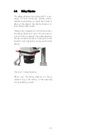
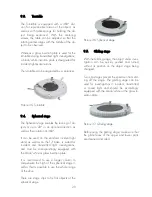
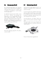
Picture 20: Transmitted light – Dark-field device
he SMT 4 and SMC 4 can be converted for
te
nation with the
ansmitted light base.
4.13. Transmitted light base
T
transmit d and mixed light illumi
tr
Please note: The transmitted light base can’t be
used in combination with the large stand!
be
rewed on to the base with both knurled
Place the incident light stand on the top of the
transmitted light base, which should then
sc
screws. Exchange the insertion plate in the
base of the stand with the glass insertion plate.
Plug the light 3W-LED or 6V/20W into the
mount on the back of the transmitted light
base. The frosted side of the mirror must be
turned towards the light. Correct the mirror po-
sition by turning the left or right adjusting knob
while looking through the microscope and ad-
just the light field size by focusing the light.
Please note: The image has the most contrast if
the light field size is the same as the field of vi-
on.
is required for mixed light. The light for
cident light illuminations remains on the mi-
si
A second light illuminator and a second power
source
in
croscope.
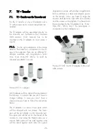
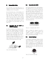
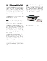
Picture 21: Transmitted light base
ident light
he T/I base presents a more comfortable
,
hich reaches an especially uniform illumina-
trical
omponents as well as connection possibilities
as to be con-
ected to the power source. The network volt-
4.14. Base for transmitted or inc
T
variation for investigations in transmitted light
w
tion of the object field and is suited for frequent
changes of transmitted and incident light.
It contains the total transmitted light units includ-
ing an illumination source and the elec
c
for an incident light illumination.
The column will set on the base and screwed
tightly. After that the T/I base h
n
age must agree with the voltage type indicated
on the bottom of the base. It is possible to
change the existing column against a column
with more length.
21


