


Page 52
Test Details:
a
. Connect the power cord from the test equipment to
the mains power inlet of the AEU-525, and the return
lead of the Ground Bond Tester to the chrome plated
bungee handle.
b.
Verify that the settings on the Ground Bond Tester
are correct (Ref. Ground Bond Tester (Preset M0-1).
c.
Press the “TEST” button on the Ground Bond
Tester and wait for the test to finish.
3. Dielectric Withstand Test - Mains to accessible
earthed metal.
Test parameters:
Test voltage 2520 VDC, Ramp 1
second, Dwell 1 second, Leakage current limit 1.0 mA,
Arc Fail is OFF.
Test Details:
a.
Connect the power cord from the test equipment to
the mains power inlet of the AEU-525, and the return
lead of the Hypot III Tester to the chrome handle
inside the ‘525.
b.
Verify that the settings on the AC/DC Withstand
Voltage Tester are correct. Press the “TEST” button
on the Dielectric Withstand Tester and wait for the test
to finish.
4. Dielectric Withstand Test
-
Mains to AEU-5000
Handmotor.
Test parameters:
Test voltage 4350 VDC, Dwell Time 1
second, Leakage current limit 1.0 mA, Arc Fail is OFF.
Test Details:
a.
Connect the power cord from the test equipment to
the mains power inlet of the AEU-525 and the return
lead of the Ground Bond Tester to the E-head of the
AEU-525 motor.
b.
Verify that the settings on the AC/DC Withstand
Voltage Tester are correct.
c.
Press the “TEST” button on the Dielectric Withstand
Tester and wait for the test to finish.
5. Dielectric Withstand test – Mains to Scaler Tip.
Test parameters:
Test voltage 4350 VDC, Ramp 1
second, Dwell 1 second, Leakage limit 1 mA, Arc Fail is
OFF.
Test Details:
a.
Make sure the power switch/circuit breaker and the
compressor circuit breaker are on.
b.
Open the transition box on the Delivery Module and
disconnect the green wire at the Euro terminal strip
and fold the wire away from any metal parts.
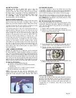
c.
Connect the appliance coupler cord from the hipot
tester to the mains input of the AEU-525. Connect the
return cable of the hipot tester to the scaler tip. Lay
the scaler handle and the return lead on a sheet of
insulator so there is no mechanical stress placed on
the scaler tip.
d.
Verify the test settings are correct. Push ‘TEST’
and wait for the test to finish.
e.
Reconnect the green wire, check continuity, and
replace transition box cover.
6. Dielectric Withstand Test - Mains to the combined
foot pedal wires.
Test parameters:
Test voltage 4350 VDC, Ramp 1
second, Dwell 1 second, Leakage limit 1 mA, Arc Fail is
OFF.
Test Details:
a.
Make sure the power switch/circuit breaker and the
compressor circuit breaker are on.
b.
Attach a foot pedal connector cable 875070 with all
wires joined to form a common test point (ATU-0076).
c.
Connect the appliance coupler cord from the hipot
tester to the mains input of the AEU-525. Connect
the return cable of the hipot tester to the joined wires
of the foot pedal connector.
d.
Verify the test settings are correct.
e.
Push ‘TEST’ and wait for the test to finish
J. Empty Water Bottle and Dry:
Make sure the electric motor is attached to the Delivery
Module and place the motor in a dry absorbent material.
Open Handpiece Water adjust all the way, open the
Handpiece Water toggle valve, press on foot pedal and
blow out water from the lines and motor. Place motor in
holder. Remove scaler from holder and open Scaler
Water adjust all the way, open the Scaler Water toggle
valve, TURN THE SCALER INTENSITY CONTROL AS
LOW AS POSSIBLE, press on foot pedal and blow out
water from the lines and scaler. DON’T OPERATE
LONGER THAN 30 SECONDS!
K. Foot Control
:
Ensure that the foot control has “PASSED” label P/N
420301.
L. Labeling and Serial Number:
Make sure all required labels, including the one with the
serial number, are present.
M.Manual and Packaging:
Ensure the instrument has one foot pedal, high vacuum
hose, low vacuum hose, 120VAC power cord, 220VAC
power cord, 40K motor, waste tank and lid, manual and
packing guide.
Refer to Schematic Drawing Set, PN 420991, Sheet 16
for test instructions on the electric motor assembly.
Refer to Schematic Drawing Set, PN 420991, Sheets 17
& 18 for setup instructions and testing parameters for
ground bond and dielectric withstand tests.
FINAL INSPECTION AND TESTING -
Cont’d