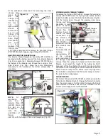
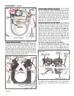
Aseptico AEU-525CF Transport III Service Manual & Parts List Download Page 19

remove  the  two

Grounding  Nuts

(PN 510293) and

Lockwashers (PN

510419). 

Re-

move  the  three

blue  female  wire

connectors  from

the 

three

terminals  on  the

power 

inlet

socket.  Set  the  Ground  Wire  aside  for  reassembly  later.

Remove  the  two  blue  flag-type  wire  connectors  from  the

terminals on the Power Entry Circuit Breaker and set the two

wires aside. Remove the six red flag-type wire connectors

from the terminals on the Compressor Breaker.
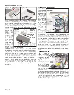
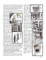
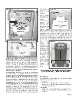
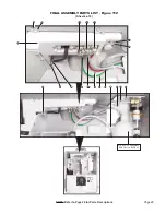
Cut  the  three  cable

ties  (PN  510137)

around  the  wire

bundles  on  the  back

side of the Panel (see

Fig.  92).  Locate  the

red and orange wires

from the Voltage Selector Switch and trace them back to the

10-position terminal block (see Fig. 92 Inset). Use a small

jeweler's screwdriver to detach the two wires from positions

#1 and #2.
At  the  Voltage  Selector  Switch  carefully  pull  the  red  and

orange wires through the terminal block grommet and all the

way through the wire bundle heatshrink tube (Fig. 93). 

green/yellow  ground  wire  from  the  Compressor  to  the

grounding hardware on the back side of the Electrical Panel,

using a 5/16" open ended wrench.
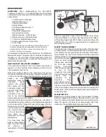
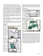
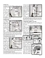
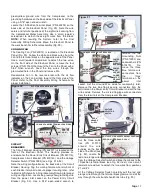
Locate the 10-Position Terminal Block (PN 860278) on the

back  side  of  the  Electrical  Panel  (Fig.  89).  Note  the  wire

colors and terminal positions of the eight wires coming from

the  Compressor  Motor  Assembly.  Use  a  small  jeweler's

screwdriver  to  detach  these  eight  wires  from  the  Block.

NOTE:

When  rewiring  the  System,  refer  to  the  Final

Assembly  Wiring  Schematic.  Move  the  Electrical  Panel  to

the work bench for further disassembly (Fig. 90).
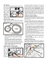
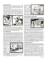
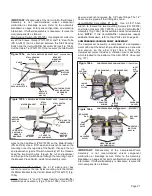
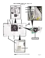
COOLING FAN

The Cooling Fan (PN 540012) is located on the Electrical

Panel (Fig. 90). Follow the white and black wires from the

Fan to the terminal block on the opposite side of the Panel.

Use a small jeweler's screwdriver to detach the two wires.

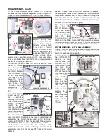
On  the  front  side  of  the  Electrical  Panel,  remove  the  four

screws (PN 510160) that mount the Fan to the Panel with a

5/64"  Allen  wrench.  Feed  the  two  wires  through  the

grommeted hole in the Panel and remove Fan.
Reassemble  Fan  in  the  reverse  order  with  the  air  flow

indicator  on  the  Fan  pointing  toward  the  front  side  of  the

Panel.  Refer  to  the  Final Assembly  Wiring  Schematic  for

proper installation.
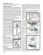
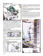
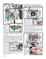
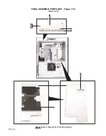
CIRCUIT

BREAKERS

The Circuit Breaker Housing (PN 462017) is located on the

front  of  the  Electrical  Panel.  The  Housing  provides  an

enclosure for the Power Entry Circuit Breaker (PN 840119),

Compressor Circuit Breaker (PN 830143), and the Voltage

Selector Switch (PN 840084) (see Figs. 91 & 92). 
Note the wiring configuration on the back side of the Circuit

Breaker Housing. Tag the mating female wire terminals at

each Breaker terminal to assure proper rewiring later - refer

to Electrical Schematic in Final Assembly Drawing for proper

wiring configuration. Locate the green/yellow grounding wire

from  the  power  inlet  socket  on  the  Power  Entry  Circuit

Breaker  (Fig.  92).  Use  a  5/16"  open-ended  wrench  to

Page 17

Figure 90

ELECTRICAL PANEL BACK SIDE

(WHT: POS 7)

COOLING

FAN

COOLING FAN WIRE/TERMINAL POSITIONS

(BLK: POS 4)

PANEL FRONT SIDE

MTG SCREWS

(X4)

Figure 91

ELECTRICAL PANEL BACK SIDE

POWER

ENTRY

GROUND

WIRE

POWER

ENTRY

CIRCUIT

BREAKER

COMPRESSOR CIRCUIT BREAKER

VOLTAGE

SELECTOR

SWITCH

POWER

INLET

SOCKET

Figure 92

(ORANGE: POS 2)

CABLE TIES

(X3)

VOLT SELECTOR WIRE/TERMINAL POSITIONS

(RED: POS 1)

VOLTAGE

SELECTOR

SWITCH

RED &

ORANGE

WIRES

Summary of Contents for AEU-525CF Transport III

Page 1: ...AEU 525CF AEU 525CFH Portable Dental System SERVICE MANUAL PARTS LIST Transport III...

Page 2: ...INSERT TUBE GUARD 14 MOTOR HOUSING COVER 14 ELECTRICAL PANEL 15 48V POWER SUPPLY 15 24V POWER SUPPLY 15 DISPLAY MODULE POWER CABLE 15 CONTROL BOARD PCB 15 WASTE CONNECTOR CABLE ASSEMBLY 16 ELECTRICAL...

Page 3: ...w all air water and wiring components as installed in the unit Individual parts are also listed and referenced to Figures with callouts in the Parts Lists A Replacement Parts List is also included Use...

Page 4: ...lve Fig 7 Turn this adjustment valve counterclockwise to increase the volume of air to the handpiece then turn it clockwise to decrease the flow Return the electric handpiece to its holder when testin...

Page 5: ...ed Area Areas that are designated for handling and working on electronic sub assemblies or their components should be marked off with signs indicating the area where ESD controls are to be enforced Th...

Page 6: ...Assy 10 Motor Housing Right Wall Assy 11 Venturi Muffler Bracket Assy 12 Compressor Vacuum Pump Assy 13 Case Assy The Waste Tank and Air Electric Manifold Block are not customer serviceable subassemb...

Page 7: ...r to the Sterilization Section in this manual for more information on motor maintenance and care Refer to the handpiece manufacturers instructions for information on handpiece maintenance and repair A...

Page 8: ...surize the water bottle and remove it from its water cap Reach up into the white cap and pull the black gasket from the cap Reassemble in the reverse order with a new gasket WATER CAP The water cap PN...

Page 9: ...e Pressure Toggle Valve PN 730014 is still a t t a c h e d Remove sleeve Clamp PN 730015 and detach the clear tubing PN AA 94C from the Toggle Valve Disconnect Rear Wall and move to work bench Remove...

Page 10: ...bly Fig 31 Loosen the small setscrew on the side of the potentio meter knob with a 1 32 Allen wrench and remove knob Remove the mounting nut on the outboard side of the Manifold Wall with a socket or...

Page 11: ...he Block is located in the pivotal housing attached to the back side of the Air Water Figure 33 Manifold Module Fig 34a Use a 5 64 Allen wrench to remove the four mounting Screws PN 510037 that attach...

Page 12: ...Housing Move the Valve and its hardware to the workbench if further disassembly is required At the workbench use a flat head screwdriver to remove the two Screws PN 510688 that mount the Floating Blo...

Page 13: ...caler Tube from the manifold Cut the Anchor Line wrapped around the standoff At the workbench disconnect the remaining two sleeve clamps and hoses from the two Fittings PN 730139 Fig 52 Use a 1 4 thin...

Page 14: ...e order adjusting the length of the Wand cord to hang suspended off the floor and then trimming the excess cord and or water line Wrap the cable tie around the scaler cord just above the grommet in th...

Page 15: ...rge foam Pad PM 462100 and replace if necessary STORAGE SHELF The Storage Shelf PN 462098 is located in the top compartment of the Transport III Case Fig 68 Use a 5 64 Allen wrench to remove the two m...

Page 16: ...k pliers to pry off the Ferrule PN 462138 and then the Fitting PN 462021 on the larger High Vacuum Hose PN AA 259 see Fig 73b Inspect O Ring PN 520101 for wear and replace if necessary Next remove Fer...

Page 17: ...7 that mount the Control Board PCB to the four Standoffs PN 510760 Next use a 5 64 Allen wrench to ELECTRICAL PANEL The Electrical Panel is located beneath the Motor Housing Cover Fig 79 Locate the Di...

Page 18: ...ator Pad PN 462080 and set aside for reuse later At the workbench cut and remove the Cable Tie PN 510628 that straps the Power Supply to the Control Board PCB Lift the Power Supply straight up and off...

Page 19: ...PN 540012 is located on the Electrical Panel Fig 90 Follow the white and black wires from the Fan to the terminal block on the opposite side of the Panel Use a small jeweler s screwdriver to detach th...

Page 20: ...capable of 22 10 AWG contour crimps When reconnecting a new flag terminal to the black wire shown here use a Molex Model 640014100 tool or equivalent tool capable of crimping flag terminals On the fr...

Page 21: ...ting Screws PN 510037 in the top left corner of the Left Wall Assembly Fig 98 Remove Screws using a 5 64 Allen wrench Locate the two 1 2 gray vacuum Hoses PN 730373 leading from the two Venturi Assem...

Page 22: ...embly later VENTURI MUFFLER BRACKET ASSEMBLY The Venturi Muffler Bracket Assembly is located on the back side of the Compressor Assembly Fig 104 Locate the Vacuum Hose PN 730130 leading from the Compr...

Page 23: ...at is attached between the Stall Sensing Switch and the Venturi Muffler Assembly 2 see Fig 105b Cut the Cable Tie PN 510137 that secures the two Switch wires to the Clip Mount PN 510759 on the Motor B...

Page 24: ...reassembly later Coupler Fitting PN 730153 Use a 5 8 open end wrench to detach the Elbow Fitting PN 730484 on the end of the Coupler then use a 3 4 wrench to remove the Coupler Place Coupler aside for...

Page 25: ...crews PN 510533 for the Bottle Storage Cap PN 462110 using a Phillips screwdriver Detach and replace Holding Strap PN 462144 as necessary Locate the Fastener Tool PN 462137 and Coiled Tether PN 520102...

Page 26: ...85 4 WASHER BLIND RIVET 1 8 510198 4 MOTOR HOUSING COVER PLASTIC AEU 525 462008 1 CABLE ASSY POWER DISPLAY MODULE AEU 525 875118 1 1 ITEM PART NO QTY 2 3 4 5 6 7 8 9 10 11 12 13 14 15 16 ITEM PART NO...

Page 27: ...s FINAL ASSEMBLY PARTS LIST Figure 112 Sheet 2 of 9 2 3 6 9 10 13 WASTE TANK ASSEMBLY NO COMPONENT BREAKDOWN 22 AIR ELECTRIC MODULE ASSEMBLY SEE FIG 113 PAGE 33 1 4 5 18 17 12 77 82 76 73 70 75 74 19...

Page 28: ...NAL ASSEMBLY PARTS LIST Figure 112 Sheet 3 of 9 AIR BOTTLE ASSEMBLY SEE FIG 114 PAGE 37 33 26 56 38 39 42 33 31 40 41 36 37 27 32 35 49 23 25 24 30 28 29 31 39 NOTE Refer to Page 24 for Parts Descript...

Page 29: ...Page 27 FINAL ASSEMBLY PARTS LIST Figure 112 Sheet 4 of 9 54 15 18 58 57 59 63 60 62 61 112 NOTE Refer to Page 24 for Parts Descriptions 78 92 113 COMPRESSOR ASSEMBLY SEE FIG 115 PAGE 38...

Page 30: ...Page 28 NOTE Refer to Page 24 for Parts Descriptions FINAL ASSEMBLY PARTS LIST Figure 112 Sheet 5 of 9 51 50 52 73 53 49 70 71 72 75 74...

Page 31: ...e 29 NOTE Refer to Page 24 for Parts Descriptions FINAL ASSEMBLY PARTS LIST Figure 112 Sheet 6 of 9 34 82 83 84 78 26 23 25 24 46 47 43 48 AIR BOTTLE ASSEMBLY SEE FIG 114 PAGE 37 44 114 114 115 116 39...

Page 32: ...Page 30 100 FINAL ASSEMBLY PARTS LIST Figure 112 Sheet 7 of 9 NOTE Refer to Page 24 for Parts Descriptions 98 107 111 110 70 71 72 102 103 104 105 101 103 104 103 104 109 108 106 99 25 106...

Page 33: ...Page 31 NOTE Refer to Page 24 for Parts Descriptions FINAL ASSEMBLY PARTS LIST Figure 112 Sheet 8 of 9 87 111 94 95 96 91 92 90 88 89 91 97 93 55 106 89...

Page 34: ...Page 32 FINAL ASSEMBLY PARTS LIST Figure 112 Sheet 9 of 9 28 67 65 66 67 68 69 111 111 85 86 NOTE Refer to Page 24 for Parts Descriptions...

Page 35: ...10768 2 WASHER NYLON 196IDX 437ODX 062T 10 FENDR 510019 2 WASHER FLAT STNLS 10 510356 3 GUARD HP TUBING AEU 525 462121 1 LABEL DELIVERY MODULE AEU 525 S CF 420596 16 1 DELIVERY MODULE HANDLE BRACKET A...

Page 36: ...OTE Refer to Page 33 for Parts Descriptions 8 11 10 27 26 72 70 73 74 75 24 81 71 26 AIR ELECTRIC MODULE ASSEMBLY Figure 113 Sheet 2 of 4 28 9 78 79 32 76 77 25 80 32 70 111 80 29 30 3 2 23 1 98 99 31...

Page 37: ...37 32 64 51 60 61 52 53 19 57 125 126 17 21 11 132 33 20 19 18 22 13 16 15 14 12 128 115 130 142 110 106 102 151 109 150 123 119 120 121 32 127 16 19 42 38 39 40 41 56 55 54 48 47 65 2 101 116 32 34...

Page 38: ...ELECTRIC MODULE ASSEMBLY Figure 113 Sheet 4 of 4 NOTE Refer to Page 33 for Parts Descriptions 128 115 87 4 91 29 6 5 106 20 107 110 86 96 132 91 90 91 92 85 32 MANIFOLD ASSEMBLY NO COMPONENT BREAKDOW...

Page 39: ...R BOTTLE AEU 525 462007 1 C S BTNSOC STNLS 8 32 X 3 8 510404 2 1 ITEM PART NO QTY 2 3 4 5 6 7 8 FTN ELBOW 90 1 4 POLY X 1 8 MPT 730120 1 FTN 1 4 POLY X 1 8 MPT POLYTITE 730117 1 LABEL FILTER DRAIN GEN...

Page 40: ...0 8333 TUBING SALIVA EJECT 3 8OD GRY AA 86G 6 0625 FTN 1 4 X 1 4 BARB STRAIGHT SS 730558 1 C S BTNSOC STNLS 6 32 X 3 8 510160 12 FTN 1 4 DELRIN SLEEVE 730095 4 TUBING AIR BRAKE 1 4 BLACK 730130 1 068...

Page 41: ...35 36 37 38 39 40 42 43 44 45 46 47 48 57 49 50 51 52 53 54 55 56 58 59 60 61 PWR ENTRY CKT BRKR SWTCH 6A 2 POLE 1 5MM 840119 1 GROMMET 1 4 DIA FOR 3 8 DIA X 095 NEOPRENE 870185 1 FAN 115 V TUBEAXIAL...

Page 42: ...2 23 42 30 47 57 26 59 58 2 1 3 1 52 53 54 55 4 5 6 5 7 8 9 8 3 56 59 5 27 9 7 30 8 31 6 32 33 44 37 45 46 24 43 48 34 35 26 32 31 28 24 29 15 16 17 37 38 36 37 38 41 39 40 60 63 63 NOTE Refer to Pag...

Page 43: ...1 ITEM PART NO QTY 2 3 4 5 6 7 8 9 10 11 12 13 14 15 16 TOP VACUUM VALVE AEU 525 462090 1 C S BTNSOC STNLS 6 32 X 3 8 510160 4 O RING 0 489 ID X 0 070 WIDE VITON 60 DUROM 520078 3 PLUNGER VACUUM VALVE...

Page 44: ...NO QTY 2 3 4 5 6 7 8 9 10 11 12 13 14 15 16 GASKET NYLON 10 730074 1 FTN ELBOW 90 1 4 POLY X 1 8 MPT 730120 3 FTN STREET TEE 1 8MPT MOD 730133 01 1 VALVE CHECK 100PSI 1 8FPT BRAS 730453 1 FTN STREET T...

Page 45: ...1 MUFFLER ASSY AMC 20 330564 2 BODY VENTURI AMC 20 461851 2 1 ITEM PART NO QTY 2 3 4 5 6 7 8 9 10 11 12 13 14 15 16 C S BTNSOC STNLS 8 32 X 1 4 510309 4 GASKET NYLON 10 730074 5 VENTURI BRACKET AEU 5...

Page 46: ...2 3 4 5 6 7 8 COLD START VALVE ASSY 1 4 MPT 330633 1 MOTOR MOUNT AEU 525 462082 2 C S BTNSOC STNLS 1 4 20 X 1 1 4 510295 4 GROMMET BUSHING SORBOTHANE 70 DURO 870315 4 GROMMET WASHER SORBOTHANE 70 DUR...

Page 47: ...2 1 ITEM PART NO QTY 2 3 4 5 6 7 8 MEMBRANE INLET POWER COVER AEU 525CF 462298 1 PLATE CLAMP WASTE MEMBRANE AEU 525CF 462316 1 MEMBRANE WASTE SENSOR COVER AEU 525CF 462299 1 FASTENER 1 4 TURN DZUS LIO...

Page 48: ...ht on the motor see Fig 124 is soft and can be damaged It should not be exposed to dust and debris Excessive dust and debris may cause a drastic decrease in optical output In the event that the light...

Page 49: ...sert a new tip press locking collar and push tip into socket as far as it will go Release ring and gently tug on tip before using to ensure that tip is securely locked into socket Syringe Tip Steriliz...

Page 50: ...ater flow control valve to the handpiece is open counterclockwise Check that handpiece air toggle on side of air electric module is On Check that the air flow control valve to the handpiece is open co...

Page 51: ...1 LITER BLOW MOLDED HDPE WATER 730471 1 GASKET FOR AIR WATER BOTTLE LID 730473 3 FILTER AIR 1 4 NPT X 1 19 GAST INLET FILTER 730494 1 ITEM PART NO QTY BOTTLE 750 ML 25 OZ BLOW MOLDED HDPE AIR 730657 1...

Page 52: ...sure switch to Pressure and verify that there is air flow from the bottle cap Switch to Purge and replace the water bottle C Performance Test Line Voltage Select 1 Turn off the compressor power switch...

Page 53: ...inal pressure of the ATU 0088 gauge It should be between 25 and 35 PSI and should be reached within 10 seconds of turn on Repeat steps 4 more times If pressure is wrong or it takes too long to pressur...

Page 54: ...aler tip Lay the scaler handle and the return lead on a sheet of insulator so there is no mechanical stress placed on the scaler tip d Verify the test settings are correct Push TEST and wait for the t...

Page 55: ...tmospheric Pressure Limitation Type BF Equipment Motor Direction Light Controls Consult Instructions For Use Do Not Lift by Top Lid Or Latches Counterclockwise to Increase Open Clockwise to Decrease C...

Page 56: ...ombination Wrenches 1 4 5 16 11 32 3 8 7 16 1 2 9 16 Qty 2 5 8 3 4 13 16 7 8 1 Screwdrivers 1 4 Standard Slot 3 64 Standard Slot Jeweler s 1 Phillips 2 Phillips Electrical Tools Wire Stripper Crimp To...

Page 57: ...C 4 to 149 F Relative Humidity 10 to 95 non condensing Altitude 0 to 3048 meters 0 to 10 000 feet SPECIFICATIONS This device has been tested and found to comply with the emissions requirements of IEC...

Page 58: ...will provide instructions usually directing that the product be returned for service Shipment to Aseptico and the cost thereof is always the responsibility of the purchaser Accidental misuse inapprop...

Page 59: ...Page 57 Notes...

Page 60: ...oodinville WA 98072 1548 1 800 426 5913 425 487 3157 Fax 425 487 2608 www aseptico com info aseptico com For Further Service And Or Technical Assistance Contact P N 420990 Rev G ECO 14684 03 2019 PRIN...

Reviews: