

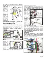

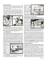
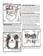


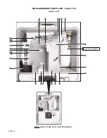

a 5/64" Allen wrench
to remove the two
mounting Screws
(PN 510037) that
attach the Baffle to
the Compressor Top
Panel.
Remove
Baffle and move it to
workbench if further
disassembly
is
required. At the
bench, use a 3/32"
Allen wrench to
remove
the
mounting
Screw
(PN 510404) from
the large Mounting Clip (PN 730445). The two smaller
Mounting Clips (PN 510699) are Riveted (PN 510772) to the
Baffle and cannot be detached. Unhook Velcro Strap (PN
462145) and replace if necessary.
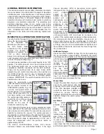
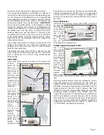
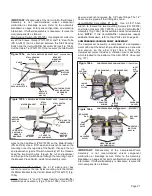
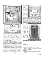
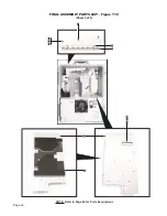
COMPRESSOR ASSEMBLY TOP PANEL
The entire Compressor Assembly can be detached and
pulled out of the Transport III Case for component
disassembly.
Use a 3/32" Allen wrench to remove the two mounting
Screws
(PN
510404) located on
the Compressor Top
Panel (see Fig.
71a). Use a 5/32"
Allen wrench to
remove all the
C o m p r e s s o r
Assembly mounting
hardware located on
the bottom of the
Case (see Fig. 71b).
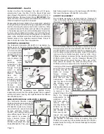
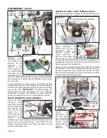
Pull the High Vacuum and Low
Vacuum Hoses down inside the
Case top compartment, to
provide
slack
when
removing the Compressor
Assembly (see Fig. 72).
Carefully pull the entire
Compressor Assembly out
of the Case and place in
front of Case temporarily.
Leave all tubing attached.
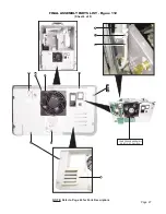
A Top Panel (PN 462063)
covers the Compressor
Assembly (Fig. 72). Use a
5/64" Allen wrench to
remove the six Screws (PN
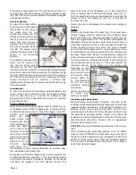
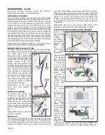
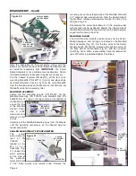
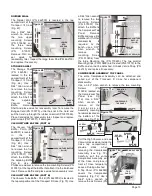
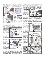
DIVIDER WALL
The Divider Wall (PN 462000) is located in the top
compartment of the
Transport III Case
(Fig. 67).
Use a 5/64" Allen
wrench to remove
the two upper
mounting Screws
(PN 510808) and
the three lower
mounting Screws
(PN
510037).
Remove Wall and
set
aside
for
reassembly later. Inspect the large foam Pad (PM 462100)
and replace if necessary.
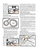
STORAGE SHELF
The Storage Shelf
(PN 462098) is
located in the top
compartment of the
Transport III Case
(Fig. 68). Use a
5/64" Allen wrench
to remove the two
mounting Screws
(PN 510037) that
attach the Shelf to
the
adjoining
Vacuum
Tube
Baffle.
Remove
Shelf and place aside for reassembly later. To remove the
Bungee Cord (PN 730370), untie the knot in the Cord and
pull the Cord up through the rubber Grommet (PN 870326).
Place Cord aside for reassembly later. Inspect and replace
plastic Hook (PN 730371) if damaged.
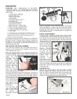
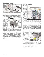
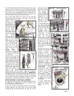
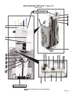
VACUUM TUBE BAFFLE (PART A)
The Vacuum Tube
Baffle - Part A (PN
4620001) is located
in
the
top
compartment of the
Transport III Case
(Fig. 69). Use a
5/64" Allen wrench
to remove the five
mounting Screws
(PN 510037) that
attach the Baffle to
the adjoining Baffle
Part B. Use a
Phillips screwdriver to remove the two mounting Screws (PN
510781) at the top of the Baffle that attach it to the Bulkhead
Insert. Remove Baffle and place aside for reassembly later.
VACUUM TUBE BAFFLE (PART B)
The Vacuum Tube Baffle - Part B (PN 4620002) is located in
the top compartment of the Transport III Case (Fig. 70). Use
Page 13
HIGH VAC HOSE
Figure 72
COMPRESSOR ASSY
Figure 67
DIVIDER
WALL
UPPER
MTG.
SCREWS
(X2)
LOWER
MTG.
SCREWS
(X3)
Figure 68
STORAGE
SHELF
MTG.
SCREWS
(X2)
BUNGEE
CORD
w/HOOK
GROMMET
VACUUM
TUBE
BAFFLE
Figure 69
VACUUM TUBE BAFFLE
(Part B)
MTG. SCREWS
(X2)
MTG.
SCREWS
(X5)
VACUUM TUBE BAFFLE
(Part A)
Figure 70
VACUUM TUBE
BAFFLE
(Part B)
LARGE MTG. CLIP
MTG. SCREWS (X2)
SMALL MTG.
CLIP (X2)
VELCRO
STRAP
Figure 71a
COMPRESSOR
TOP PANEL
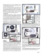
Figure 71b
MOUNTING
HARDWARE
MOUNTING
SCREWS
BUSHING
(PN 520118)
WASHER
(PN 510837)
SCREW
(PN 510294)
SCREW
(PN 510295)
BUMPER
(PN 850082)
WASHER
(PN 510837)
BUSHING
(PN 520118)
LOW VAC
HOSE
TOP
PANEL