


Ascon Tecnologic - Y39H Line - Operating Instructions - Pag. 7
turned ON again, the timer status must therefore be that in
which it was when it was turned OFF. If the timer is ena-
bled and the auxiliary output command is configured to be
enabled via key ( or ) or digital input, the command
given by these inputs resets the timer count by activating
the
Aux
output (if OFF) or deactivating the
Aux
output (if
ON). This mode can be used to activate cyclic actuators
such as, for example, fans and shutters for environment
air exchange or servomechanisms for the materials rota-
tion devices (e.g.: eggs incubators or test tubes);
off
Aux
ON
ON
ON
o.tn
o.tF
off
o.tn
o.Fo
=
2
o.tF
off
o.tn
o.tF
3.
Twin timer dependent on temperature control. The
Aux
output is activated in conjunction with the activation of the
ot
temperature control output. When the
ot
temperature
control output is active, the
Aux
output is always active.
On the other hand, when the ot output is disabled, the
Aux
output is activated and deactivated cyclically accord-
ing to the times set at
o.tn
and
o.tF
parameters.
Therefore, when the output ot is de-activated, the
Aux
output remains active for the time o.tn, then is de-activat-
ed for the time
o.tF
, re-activated for the time
o.tn
and so
on until the output
ot
is activated on temperature control
request and consequently the
Aux
output is re-activated,
regardless of the times
o.tn
and
o.tF
.
The internal buzzer (when present) can be configured by
parameter
o.bu
to carry out the following functions:
of
Buzzer always disabled;
1
The Buzzer sounds when an alarm is active;
2
The Buzzer sounds when a key pressed (no alarm);
3
The Buzzer sounds when a key pressed and when an
alarm is active.
5.5
Temperature Control
The instrument adjustment method can be selected using
the
r.HC
parameter and acts on the outputs configured as
ot
and
HE
according to the temperature measurement, the
SPt
Set Point and the parameters that follow.
5.5.1 ON/Off temperature control
(
R.HC
=
H
or
C
)
In case of ON/OFF temperature control (
r.HC
=
H
or
C
) the
controller acts depending on the
r.d
differential (histeresys)
which is automatically considered by the controller with
posi-
tive
values for
Cooling
actions (
r.HC
=
C
) or with
negative
values for
Heating
actions (
r.HC
=
H
).
r.HC
=
C
OUT
ot
SPt
Temp.
r.d
time
r.HC
=
H
off
off
SPt
r.d
ON
ON
ON
OUT
ot
off
off
ON
ON
ON
time
Pt
Temp.
Pt
5.5.2 ON/Off temperature control with neu-
tral zone
(
r.HC
=
nr
)
When
r.HC
=
nr
, the output configured as
ot
operates with
a cooling action (like
r.HC
=
C
) while the output configured
as
HE
can be used to operate with a heating action. The
r.d
differential intervention is automatically assumed by the
controller to have positive values for the cooling action and
negative values for the heating action.
Spt
Output
off
off
ON
Temp.
time
r.d
r.d
ON
off
off
ON
r.HC
= nr
Pt
HE
ot
The time protections described below (
P.t1
/
P.t2
) always and
only act on the output configured as
ot
and only in ON/OFF
control (
r.HC
=
C
,
H
,
nr
).
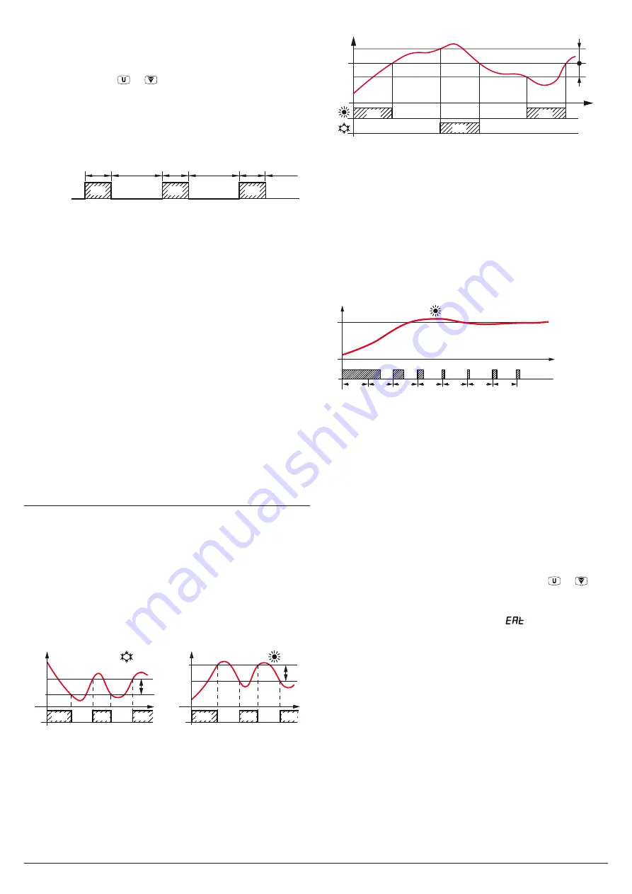
5.5.3 Single action PID temperature control
(
r.HC
=
HP
or
CP
)
The instrument single action PID control algorithm provides
for the setting of the following parameters:
r.d
Proportional band;
r.td
Derivative time;
r.ti
Integral time;
r.tC
ot
output cycle time.
Temp.
SPt
Pt
time
ON
ON
ON
ON
ON
ON
ON
off
off
off
off
off
off
r.tC
off
Out
(
ot
)
r.HC
= HP
r.tC
r.tC
r.tC
r.tC
r.tC
r.tC
Example of PID control with Heating action.
When PID control is choosen, the
Autotuning
function is
available which allows the automatic tuning of the above
parameters. To activate the
Autotuning
function:
–
Set and activate the desired Set Point SPt;
–
Set the
rH
parameter.
r.HC
=
HP
(if the control is heating)
or
r.HC
=
CP
(if the control is cooling);
–
Set the
r.At
parameter as:
1
The Autotuning is started automatically every time the
instrument is turned on;
2
The Autotuning is started automatically the next time
the instrument is turned ON and, once the tuning is
finished, the
r.At
parameter is automatically set to
of
;
3
The Autuning is manually started using the or key
(when appropriately configured as
t.UF
or
t.Fb
=
3
).
If the Autotune process is not completed within 12 hours, the
instrument will showthe error message
EAt
on the display.
In case of probe error, the instrument automatically stops the
cycle in progress.
The values calculated by Autotune are automatically stored
in the instrument memory at the end of the correct PID pa-
rameters tuning.
Autotune in progress is indicated by the
At
label, alternated
every 10 s with the normal display value
In the event of a probe error (in all control modes), it is possi-
ble to make the output configured as
ot
continues to operate
cyclically according to the times programmed with param-
eters
r.t1
(activation time) and
r.t2
(deactivation time).
When an error occurs to the
Pt
temperature probe, the in-
strument activates the
ot
output for the time set at
r.t1
, then
deactivates it for the time set at
r.t2
and so on until the error
persists.
By programming
r.t1
=
of
the
ot
output in probe error con-


