


Ascon Tecnologic - KX5P Line - ENGINEERING MANUAL - PAG. 11
[26] o4.AL - Alarms linked up with Out 4
Available:
When [24] o4F = AL.
Range:
0... 63 with the following rule:
+1 Alarm 1;
+2 Alarm 2;
+4 Alarm 3;
+8 Loop break alarm;
+16 Sensor break (burn out);
+32 Overload on Out 4 (short circuit on OP4).
For more details see [17] o1.AL parameter.
[27] o4Ac - Out 4 action
Available:
When [25] o4F is different from
nonE
.
Range:
dir
Direct action;
rEU
Reverse action;
dir.r
Direct action with revers LED indication;
rEU.r
Reverse action with reverse LED indication;
For more details see [18] o1.Ac parameter.
]
AL1 Group - Alarm 1 parameters
[28] AL1t - Alarm 1 type
Available:
Always.
Range: •
When one or more outputs are programmed as
control output:
nonE
Alarm not used;
LoAb
Absolute low alarm;
HiAb
Absolute high alarm;
LHAo
Absolute band alarm with alarm indication
out of the band;
LHAi
Absolute band alarm with alarm indication
inside the band;
SE.br
Sensor break;
LodE
Deviation low alarm (relative);
HidE
Deviation high alarm (relative);
LHdo
Relative band alarm with alarm indication
out of the band;
LHdi
Relative band alarm with alarm indication
inside the band;
• When no output is programmed as control output:
nonE
Alarm not used;
LoAb
Absolute low alarm;
HiAb
Absolute high alarm;
LHAo
Absolute band alarm with alarm indication
out of the band;
LHAi
Absolute band alarm with alarm indication
inside the band;
SE.br
Sensor break.
Notes: 1.
The relative and deviation alarms are “relative” to
the operative set point value.
LoAb
OUT
AL1
AL1
PV
HAL1
time
HiAb
OUT
AL1
AL1
PV
HAL1
time
LHAb
PV
AL1H
HAL1
time
off
off
off
LHde
OUT
AL1
AL1L
HAL1
PV
AL1H
SP
HAL1
time
OUT
AL1
AL1L
HAL1
off
off
off
ON
ON
ON
ON
off
off
off
off
off
off
ON
ON
ON
ON
2.
The (SE.br) sensor break alarm will be ON when
the display shows
----
indication.
[29] Ab1 - Alarm 1 function
Available:
When [28] AL1t is different from
nonE
.
Range:
0... 15 with the following rule:
+1 Not active at power up;
+2 Latched alarm (manual reset);
+4 Acknowledgeable alarm;
+8 Relative alarm not active at set point change.
Example:
Setting Ab1 equal to 5 (1 + 4) the alarm 1 will be
“not active at power up” and “Acknowledgeable”.
Notes: 1.
The “
not active at power up
” selection allows to
inhibit the alarm function at instrument power up
or when the instrument detects a transfer from:
• Manual mode (
oplo
) to auto mode;
• Stand-by mode to auto mode.
The alarm will be automatically enabled when
the measured value reaches, for the first time,
the alarm threshold ± hysteresis (in other words,
when the initial alarm condition disappears).
PWR ON
AL1
PV
time
off
off
Ab1 = +1
Ab1 = +0
off
off
ON
ON
ON
2.
A “
Latched alarm
” (manual reset) is an alarm
that will remain active even if the conditions that
generated the alarm no longer persist. Alarm
reset can be done only by an external command
(
button, digital inputs or serial link).
Alarm reset
Alarm reset
AL1
PV
time
off
off
Ab1 = +2
Ab1 = +0
off
off
ON
ON
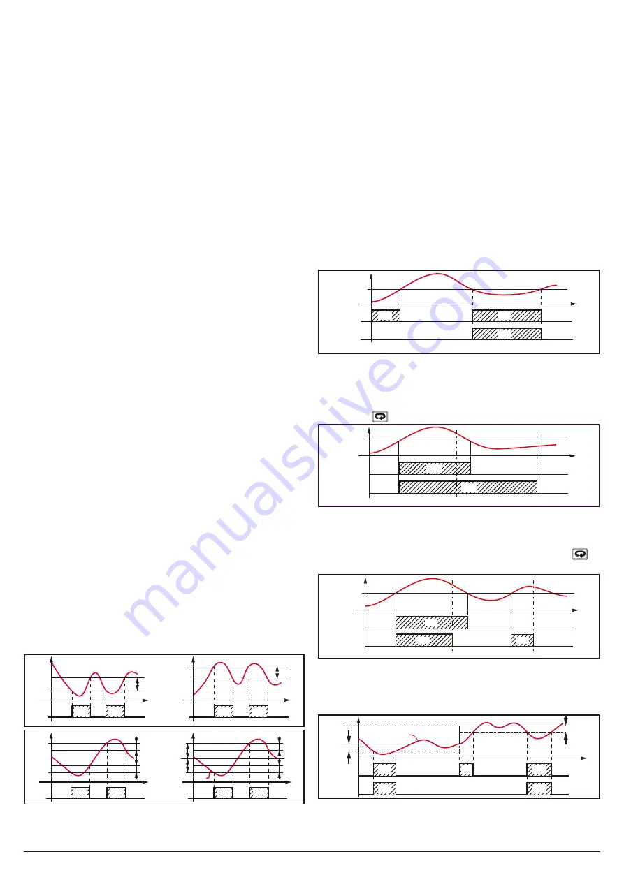
3.
An “
Acknowledgeable
” alarm is an alarm that can
be reset even if the conditions that generated
the alarm are still present. Alarm acknowledge
can be done only by an external command (
button, digital inputs or serial link).
Alarm ACK
Alarm ACK
AL1
PV
time
off
off
Ab1 = +4
Ab1 = +0
off
off
off
ON
ON
ON
A “
Relative alarm not active at set point change
”
is an alarm that masks the alarm condition after
a set point change until process variable reaches
the alarm threshold ± hysteresis.
Sp2
Sp1
PV
time
Ab1 = +8
Ab1 = +0
ON
off
off
AL1
off
off
off
AL1
ON
ON
ON
ON
4.
The instrument does not store in EEPROM the
alarm status. For this reason, the alarm status
will be lost if a power down occurs.