background image

Operating Instructions for Ascoline 700, AGH 2xx, 4xx, 6xx 

ascobloc 

Gastro-Gerätebau GmbH 

D-01156 Dresden, Grüner Weg 29 

Germany 

Tel. +49 351 4533-0 

Fax:  +49 351 4537-339 

E-mail: 

[email protected]


AGH2XX.doc, Status: 23.05.2013  

Subject to change without notice! 


4.2  Connections 

Details  of  connections  for  the  media  can  be  taken  from  the  accompanying  connection  diagram  and 
equipment description. Check whether the size and position of the electrical connections of the customer 
side correspond to the information in the connection plan, equipment description or installation plan 
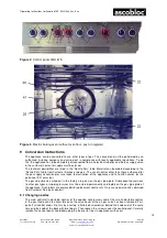
The  terminal  box  for  the  connections  is  located  behind  the  front  panel  A  (see  data  sheet).  Make  the 
connections  as  shown  in  the  annex  or  in  the  connection  diagram  accompanying  the  equipment.  The 
number of the connection diagram is to be found on the type plate. Once the electrical connections have 
been made, close the cover of the terminal box and screw the front panel in place again 

Gas type, connection pressure 

The  type  of  gas  and  the  supply  pressure  must  match  the  gas  setting  given  on  the  appliance.  If  not,  a 
conversion  or  adaptation  of  the  appliance  must  be  made  to  suit  the  local  conditions  (see  conversion 
instructions). 

Local gas conditions 

You can get the necessary technical data about the type of gas and its pressure from your gas supply 
utility. 

Extraction of flue gas 

Gas ranges are of Type “A”, i.e. the connection to a flue gas system is not required. 

Ventilation of the rooms where the appliances are set up has to comply with the regulatory guidelines in 
the DVGW Worksheet G 634. 

4.2.1  Free-standing appliances 

The  connections  can  be  made  from  below  or  from  the  rear  from  a  closed  installation  space.  With  the 
connection from below, the pipe length must be 50 mm above the floor surface. 

4.2.2  Wall/table  mounted  appliance  -  attached  to  an  installation  wall,  cantilever  or  wall-mounted 

frame 

When attaching the appliance to an installation wall, cantilever or on a wall-mounted frame (ACC 881), 
the appliance connections from below or from the rear are to be used. 

4.2.3  Wall/table-top appliances connect through the rear wall 

On the right side at the rear in the corner is a bracket that is screwed on with downwards penetration that 
covers the access to the installation channel to the rear. Remove the bracket, turn it through 180° and 
screw it back on so that the penetration in the bracket now frees up access to the rear and covers the 
downwards access. 

5  Proper Use of the Equipment 

5.1  Operational start-up 

  Remove the protective film before bringing into operation. 

  Clean the equipment with dilute soap solution. 

  Open the gas supply valve on the customer side. 

5.2  Functional test 

5.2.1  Gas range 

Check that the burner cover is correctly seated. 

Check  the  supply  pressure  (flow  pressure):  Connect  the  pressure  gauge  to  the  pressure  measuring 
nipple of the main gas pipe. 
Bring the burners into operation and check whether the allowable supply pressure is maintained. 

Check  whether  the  nozzles  appropriate  to  the  gas  supply  have  been  installed  (see  conversion 
instructions).  Close  the  sealing  screw  of  the  pressure  measuring  nipple  again  once  the  measuring  is 
finished! 
Bring  all  burners  into  operation.  There  is  air  in  the  lines  prior  to  the  first  ignition  so  it  takes  somewhat 
longer till the pilot flames can be ignited.  
Check for ignition from the pilot to the main burner, through-ignition and a regular flame pattern. 


Summary of Contents for ASCOLINE 700 Series

Page 1: ...Operating Instructions ASCOLINE 700 AGH 2xx 4xx 6xx Gas Ranges Quality and Competence in Stainless Steel 1 ...

Page 2: ...ting cleaning and repair 3 3 3 Instructions for transport 4 4 Installation 4 4 1 Setting up 4 4 2 Connections 5 5 Proper Use of the Equipment 5 5 1 Operational start up 5 5 2 Functional test 5 5 3 Operating 6 5 4 Cleaning 7 6 Repair and Maintenance 7 6 1 Repair and maintenance 7 6 2 Measures to be taken for longer stoppages 7 7 Faults and their Rectification 8 7 1 Fault rectification 8 7 2 Custome...

Page 3: ... equipment into operation for the first time It contains important instructions on setting up use and maintenance of the equipment Pay special attention to the safety instructions included in the text Keep these operation instructions in a safe place and ensure that they are accessible to the operating personnel at all times In addition to the instructions for operating you will also find instruct...

Page 4: ...except those normally used in cooking The temperatures necessary for cooking processes inevitably mean that various top surfaces and panel parts can become very hot This is not a design defect it is simply a physical fact Technical modifications to the equipment by unauthorised persons without written permission from the manufacturer completely nullify any claims under the guarantee and invalidate...

Page 5: ...iable for damage due to inexpert transport and installation Claims made under the guarantee in such cases are also invalid Gas transporting elements and electrically live components may only be installed replaced or modified by authorised specialist staff The appliance must be set up in a well ventilated room if possible under an extraction hood see DVGW Worksheet G 634 The technical data for elec...

Page 6: ...The connections can be made from below or from the rear from a closed installation space With the connection from below the pipe length must be 50 mm above the floor surface 4 2 2 Wall table mounted appliance attached to an installation wall cantilever or wall mounted frame When attaching the appliance to an installation wall cantilever or on a wall mounted frame ACC 881 the appliance connections ...

Page 7: ...e within the customer s supply 5 3 2 Baking oven optional Electric roasting and baking oven If the oven has convection heating as an extra the changeover switch 6 must be in mode II The temperature is set by turning the knob temperature controller separately for top heat 2 and bottom heat 3 When the oven is switched on the green or the yellow light is on When the preselected temperature is reached...

Page 8: ... should be cleaned daily after use The seats at the sides for the containers can be disengaged taken out and cleaned in the dishwasher The oven floor can also be removed Spray grids and surfaces of the oven with commercially available stainless steel cleaner or oven cleaner1 spray on close the oven door and leave for 10 to 20 minutes to take effect Then clean with a coarse sponge and wipe out with...

Page 9: ...is not producing any heat Power connection to equipment interrupted Fuse in customer supply is open Green indicator light is on but there is no heat heating element faulty Restore supply Restore supply Replace heating element Gas fired oven burner goes out while in service or when the oven door is being closed Inadequate ventilation in the room air extraction is switched off Make sure the room is ...

Page 10: ...H D 01156 Dresden Grüner Weg 29 Germany Tel 49 351 4533 0 Fax 49 351 4537 339 E mail service ascobloc de AGH2XX doc Status 23 05 2013 Subject to change without notice 9 7 2 Customer service ascobloc Customer Service Tel 49 351 4533 384 Fax 49 351 4533 379 E mail kundendienst ascobloc de ...

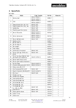
Page 11: ... Burner cover D 10 1091 13 Pot support 08 1664 14 Door handle 08 1069 15 Knob for gas thermostat AGH 417 617 10 1371 16 Scale ring for gas thermostat AGH 417 617 10 1372 17 Knob 09 2662 18 Scale ring top and bottom heat convection air temperature AGH 413 415 615 08 2909 19 Scale ring for all gas valve 08 6394 20 Scale ring for electric thermostat 08 2909 21 Knurled knob AGH 218 418 618 08 1320 22 ...

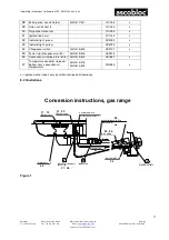
Page 12: ...re limiter AGH 415 615 09 1687 x 47 Temperature controller top and bottom heat convection air temperature AGH 413 415 AGH 613 615 09 2085 x x replacement or repair only by authorised specialist company 8 2 Illustrations Zündbrenner mit Zündbrennerkappe Hauptdüse Kleinbranddüse Gashahn PEL 21S Schlauchleitung Flachdichtung Brennerdeckel Überwurfmutter M16x1 5 SW 19 Doppelkegelring 10 mm Verschlußsc...

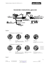
Page 13: ...and 8 nach links ca 80 drehen Vollbrandstellung 8 Knebel im Bereich von ca 140 nach links zwischen Stellung 8 bis 1 rasterartig Kleinbrandstellung 1 Zwischenbereiche stufenlos einstellbar Figure 3 Conversion instructions gas oven Oven burner Pilot burner Nozzle holder Inner nozzle Main gas line Olive 10 mm Union nut M16x1 5 A F 19 Thermocouple Nozzle Pilot gas line Retaining screw M10x1 Air regula...

Page 14: ...ustomer Service or dealers The use of nozzles other than those authorised for the gas supply correction pressure leads to destruction of the appliance and to health hazards for the personnel CO emission The gas adjustments carried out in the factory are given on the gas type plate Subsequent conversions to other gas types or supply pressures must be entered permanently and legibly on the gas type ...

Page 15: ...from above Remove the pot grid support and pull off the pilot burner cap C Loosen the plug screw at the top A F 14 and unscrew the pilot burner nozzle using a long box spanner A F 5 5 with clamping ring whenever possible 9 4 Oven burners See figure in conversion instructions for gas range with gas fired oven The main nozzle F of the oven burner is behind the lower front panel Once the lower front ...

Page 16: ...ners 6620 000 AGH 418 Gas range 4 burners 6621 000 AGH 618 Gas range 6 burners 6625 000 satisfy the provisions of the EC Gas Appliances Directive EU2009 142 EC the EMC Directive 2004 108 EC the Low Voltage Directive 2006 95 EC including modifications valid at the time of the declaration The following harmonised standards were applied DIN EN 203 1 2009 11 Gas heated catering equipment Part 1 Genera...

Page 17: ...ubject to change without notice 16 DIN EN 55014 2 2009 06 Electromagnetic compatibility Requirements for household appliances electric tools and similar apparatus Part 2 Immunity The following national or international standards or parts clauses thereof and specifications were applied DIN 18851 2003 06 Equipment for commercial kitchens Ranges Requirements and testing Dresden 23 05 2013 p p R Ziegl...

Reviews: