Asami AMV6 Service Manual Download Page 143

Gree                                                GMV6 DC Inverter VRF Units Service Manual 


141 

2.95 "J4" Compressor 4 Over-current Protection 

Fault display:

 main board of outdoor unit, wired controller of indoor unit and receiver of indoor unit 

display 


Fault diagnosis: 

When the operating current of the compressor detected by the current sensor or circuit exceeds the 

limit, the unit will stop working. 

Possible causes: 

■ The unit's parameters are abnormal;


■ The drive module is abnormal;


■ The compressor is abnormal.
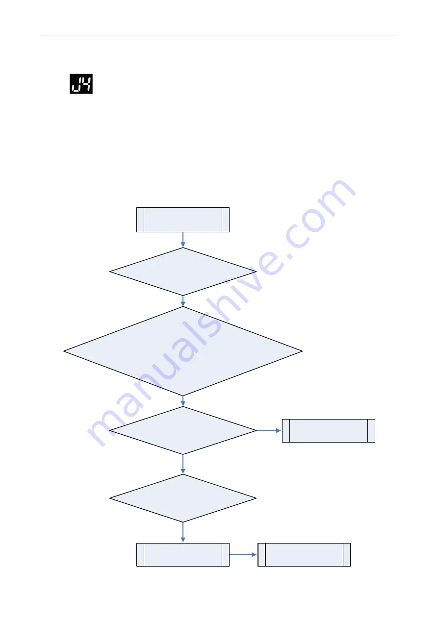
 

Troubleshooting:


"J4" Compressor 4 

Over-current Protection

The co mpr essor is 

abn ormal

Yes

Yes

Replace  th e compre ssor

No

Replace  th e d rive  modu le

If  th e h igh  pressu re valu e o f  th e u nit 

is still a bove 60°C when the compre ssor runs at the lowest 

frequen cy, the compre ssor may ha ve ena bled normal over-current 

protection. In this case, check whether th e fan oper ate s prop erly an d 

whether  th e a mb ient temperature  is n ormal  and  wh eth er the 

power supply is normal (320V-460V)

Power on aga in 

the units based on th e capa city

 and  nu mb er o f  indoo r u nits  enable d 

previou sly  in the  case o f 

protection state

Whether  th e d rive  modu le i s  normal?

Yes

Yes

Is th e p rotection still occurring 

afte r  po we r-on?

Yes


Summary of Contents for AMV6

Page 1: ...AMV6 DC Inverter VRF Units Capacity 22 4kW 246 0kW Rated Frequency 50Hz 60Hz Operation Range Cooling 5 55 C Heating 30 24 C Service manual 2021 v...

Page 2: ...ter 4 Maintenance 178 1 Precautions for Refrigerant Leakage 178 2 Refrigerant Charging 178 3 Refrigerant Charging Method 180 4 Inspection of Key Parts 183 5 Replacement of Key Unit Parts 240 6 Explosi...

Page 3: ...unctioning or damage to the air conditioning system or even personal injury Safety Instructions Warning symbols Symbols in this document indicate different severities and possibilities DANGER Indicate...

Page 4: ...30WM H X 26 10 16 GMV 730WM H X 60 16 22 22 GMV 1680WM H X 28 10 18 GMV 784WM H X 62 18 22 22 GMV 1734WM H X 30 10 20 GMV 840WM H X 64 20 22 22 GMV 1790WM H X 32 10 22 GMV 895WM H X 66 22 22 22 GMV 18...

Page 5: ...ation range C 5 55 5 55 5 55 5 55 Heating operation range C 30 24 30 24 30 24 30 24 Refrigerant type R410A R410A R410A R410A Refrigerant charge kg 5 5 5 5 7 5 7 5 Maximum drive IDU NO unit 13 16 19 23...

Page 6: ...M H X GMV 280WM H X GMV 504WM H X GMV 280WM H X GMV 560WM H X GMV 280WM H X GMV 615WM H X Cooling capacity Rated kW 68 73 78 4 84 89 5 Heating capacity Rated kW 39 52 39 52 47 2 47 2 49 2 Max kW 76 5...

Page 7: ...1855 Net weight kg 595 655 655 705 Gross weight kg 620 685 685 735 Model GMV 1175WM H X GMV 1230WM H X GMV 1290WM H X GMV 1345WM H X HP HP 42 44 46 48 Combination mode 20 22 22 22 10 16 20 10 16 22 GM...

Page 8: ...830 1855 1400 830 1855 1000 830 1855 1400 830 1855 1400 830 1855 Net weight kg 895 925 930 950 Gross weight kg 935 965 970 990 Model GMV 1630WM H X GMV 1680WM H X GMV 1734WM H X GMV 1790WM H X HP HP 5...

Page 9: ...1690 1340 775 1690 930 775 1690 1340 775 1690 1340 775 1690 1340 775 1690 Packing dimensions W D H mm 1400 830 1855 1400 830 1855 1400 830 1855 1000 830 1855 1400 830 1855 1400 830 1855 1400 830 1855...

Page 10: ...27 41 26 85 27 41 27 41 27 41 27 41 27 41 27 41 27 41 Rated current A 39 3 49 49 49 47 49 49 49 48 49 49 49 49 49 49 49 Cooling operation range C 5 55 5 55 5 55 5 55 Heating operation range C 30 24 30...

Page 11: ...rovement Please refer to nameplates of the units 3 The Range of Production Working Temperature Cooling Heating Ambient temperature 5 C 55 C DB 30 C 24 C DB Indoor temperature 14 C 25 C WB 15 C 27 C DB...

Page 12: ...eparation before commissioning Verification of installation Unit checking Commissioning 2 Safety Requirements WARNING Safety measures must be taken for outdoor operations All involved commissioning pe...

Page 13: ...e GMV6 DC Inverter VRF Units Service Manual 11 3 Unit Commissioning 3 1 Preparation 3 1 1 Tools Name Picture Screwdrivers Spanner Hex key Pincers Vacuum pump Electronic balance Pressure gauge Multimet...

Page 14: ...ng meeting Minutes of the commissioning scheme determining meeting for XXX project Theme xxx Date xxx Place xxx Participants xxx Details xxx 1 2 3 Checklist of the commissioning system appearance Chec...

Page 15: ...ndoor units Status Parameter Unit Before Startup 30 min 60 min Status parameters of the outdoor unit Outdoor ambient temperature C Power voltage V Frequency Hz Compressor current A Discharge temperatu...

Page 16: ...50 135 50 to 135 8 Is the fresh air unit access capacity within 30 30 9 Is GMV6 connected to outdoor units in other series GMV6 cannot be connected to outdoor units in other series 10 Does the drop b...

Page 17: ...r valve leakage with soap bubbles or a leak detector If leakage is confirmed stop subsequent commissioning at once and continue the work only after the problem is solved 20 Is the outdoor unit being w...

Page 18: ...between the indoor unit and the wired controller correct 36 Is the last communication indoor unit installed with a communication build out resistor 37 The communication cable cannot be laid in the sam...

Page 19: ...ps wire ends and clamps should be removed from the body 6 Check if the terminals of the electrical components in the unit are loose and the phase sequence is correct 7 Before debugging all pipeline va...

Page 20: ...us between the indoor unit and the wired controller and the indoor unit can be commissioned without a wired controller Commissioning exit In commissioning status press and hold the SW3 confirm button...

Page 21: ...CH ON Indoor outdoor unit s rated capacity ratio is too high db ON 05 ON CL ON Indoor outdoor unit s rated capacity ratio is too low db ON 05 ON OC ON System inspection is finished Enter into the nex...

Page 22: ...he indoor unit s pipeline is abnormal XXXX indicates the engineering number of fault indoor unit Error code U8 is displayed after 2s For example if the U8 fault occurs in the No 100 indoor unit LED3 d...

Page 23: ...g Progress LED1 LED2 LED3 Code Display status Code Display status Code Display status 01_ set up master unit db ON 01 ON CC ON Mater module hasn t been set in the system It needs to reset it db ON 01...

Page 24: ...lows The unit automatically enters the next step of debugging Debugging code Progress code Status code Progress LED1 LED2 LED3 Code Display status Code Display status Code Display status 04_indoor uni...

Page 25: ...status 06_outdoor unit s parts inspection db ON 06 ON OC ON The system detected that there s no fault for outdoor unit s parts Then it will automatically enter into the next step If an abnormality is...

Page 26: ...eat confirmation db ON 08 ON OC ON Compressor s preheat time has reached 2h and then it will enter into the next step If the preheat time for compressor hasn t reached 2h there will be abnormal phenom...

Page 27: ...l At this time it is necessary to check whether the gas valve and the liquid valve are completely open or whether the main pipeline is blocked Once inspection is completed you can return to the previo...

Page 28: ...t will display like that circularly Note In the pilot run stage the unit will display corresponding procedures according to actual circumstances Once debugging is completed resume the standby status a...

Page 29: ...modules are set uniformly the static pressure value of each module remains the same When a static pressure value is set in either of the two modes the previous mode setting limit is automatically rele...

Page 30: ...2 LED3 Function code Display status Mode Display status Current status Display status 1G On ADD On 00 Blinks 1G On ADD On 01 Blinks 1G On ADD On 02 Blinks 1G On ADD On 03 Blinks 1G On ADD On 04 Blinks...

Page 31: ...Start to enter the commissioning function Click Start to enter the commissioning function and the software automatically performs commissioning indicates that commissioning is being performed on the...

Page 32: ...detected on this phase which provides references for selection Click Close to close the information the number of commissioning units is displayed in 3 Confirm number of outdoor basic modules and 4 Co...

Page 33: ...phase and troubleshooting is required after troubleshooting the unit automatically enters the next step if no OK exists or click OK to enter the next step Click to display relevant information detect...

Page 34: ...rs in step 10 click Back to return to step 9 and then click OK in step 9 to perform commissioning again for step 10 If a U6 fault valve exception occurs in step 10 users can click Skip to skip the fau...

Page 35: ...ing When the system runs for 60 minutes without exception it determines that the refrigerant is normal the unit is shut down and the commissioning is completed Alternatively after staying for 65 minut...

Page 36: ...Using Multi functional Debugger Step 1 Connect multi functional debugger For details see the user manual of multi functional debugger Step 2 Set the address DIP switch SA8 of the master outdoor unit t...

Page 37: ...the product is used the cable connection of the air conditioner unit must be recovered Otherwise the actual use will be affected 3 2 6 After Commissioning Organize and save the data Make complete and...

Page 38: ...the system operates in cooling mode the temperature of the defrosting temperature sensor is 5 C to 11 C lower than the high system pressure When the system operates in heating mode the difference bet...

Page 39: ...ndoor unit parameters Inlet pipe temperature of the indoor heat exchanger C Based on the ambient temperature the inlet pipe temperature of the same indoor unit in cooling mode is 1 C to 7 C lower than...

Page 40: ...e master module SA8 DIP switch must be reset in the project SA1 DIP switch cannot be changed The default settings of other DIP switches do not need to be changed if there are no special requirements 4...

Page 41: ...odule in power off state in a refrigerating system The setting method is as follows Master Module Setting DIP Switch SA8_MASTER S DIP1 DIP2 Remarks 0 0 Master module 1 0 Submodule When delivered all m...

Page 42: ...d b submodules White lever position White lever position ON 0 0 SA8_MASTER S White lever position White lever position ON 1 0 SA8_MASTER S 4 2 System Function Operations CAUTIONS System function setti...

Page 43: ...nly be set n0 Auto energy saving This function can automatically reduce power consumption of the unit based on system operating parameters 01 Capability priority control This function can be set and q...

Page 44: ...g heating of the entire system A2 Blinks 00 Blinks 00 Blinks Refrigerant recycle A8 Blinks 00 Blinks 00 Blinks After sales vacuum pumping n0 Blinks 01 Blinks 00 Blinks Auto energy saving n3 Blinks 00...

Page 45: ...re setting 1H On 00 Blinks 00 Blinks Efficient module rotation 4n On 00 Blinks 00 Blinks Adaptive control of noise 4q On 00 Blinks 00 Blinks Forced switch of the electric heater of an indoor unit 5L O...

Page 46: ...xit the function setting status If you do not press any button in 5 minutes the system will automatically exit the current screen and the unit will resume displaying the current status Indoor unit pip...

Page 47: ...cess or exit the function setting status Note Before the refrigerant recycle of a basic module the liquid pipe stop valve of the basic module must be closed After refrigerant recycle the system cannot...

Page 48: ...status The master unit memorizes this setting and does not clear it even upon power failure and power on again The default value is nA cooling and heating mode 4 2 3 3 A7 Outdoor Silence Mode Introduc...

Page 49: ...D1 LED2 LED3 Function code Display status Silence mode code Display status Current status Display status A7 On 00 Blinks OC Blinks A7 On 01 Blinks OC Blinks A7 On 02 Blinks OC Blinks A7 On 03 Blinks O...

Page 50: ...nd all modules display as follows LED1 LED2 LED3 Function code Display status Current process Display status Current status Display status A8 On 00 On OC On At this time the expansion valves of all in...

Page 51: ...defrosting the system automatically exits according to the exit conditions and then automatically runs according to the system conditions Setting steps Step 1 Enter n3 forced defrosting and ensure th...

Page 52: ...s Current process mode Display status Current status Display status n4 On 10 On OC On n4 On 09 On OC On n4 On 08 On OC On If you do not press any button on the master unit in 5 minutes the system will...

Page 53: ...ic module is subject to the last received set value Setting steps Enter the function setting The master unit displays as follows LED1 LED2 LED3 Function code Display status Current process Display sta...

Page 54: ...LED3 Function code Display status Current module Display status One button drainage code Display status qJ On OF Blinks 00 Blinks Press the SW3 confirm button The master unit displays as follows LED1...

Page 55: ...operation of compressor 1 is shielded C8 On 02 Blinks OC Blinks The operation of compressor 2 is shielded After selecting the corresponding value press the SW3 confirm button All modules display as fo...

Page 56: ...status Current status Display status C9 On 00 Blinks OC Blinks Press the SW1 up button and the SW2 down button to select the corresponding compressor emergency operation status LED1 LED2 LED3 Descrip...

Page 57: ...mergency Operation This function is after sales emergency setting when a module works abnormally It shields the abnormal module in a short time to ensure the emergency operation of other modules Setti...

Page 58: ...hours the entire system is stopped and the indoor unit displays the Ad limit operation code 4 2 3 14 4J Emergency setting of components Emergency setting of components The emergency setting of compon...

Page 59: ...2 3 15 1F SRL Low Pressure Control Setting steps Enter the function setting The master unit displays as follows by default and other basic modules display normal working status LED1 LED2 LED3 Function...

Page 60: ...us 1H On 00 On OC On 1H On 01 On OC On The master unit memorizes this setting and does not clear it even upon power failure and power on again The default value is 00 4 2 3 17 4n Adaptive Control of N...

Page 61: ...4q On 01 Blinks OC Blinks Forced off of the electric heater of an indoor unit in full temperature range 4q On 02 Blinks OC Blinks Forced off of the electric heater of an indoor unit above 2 C outdoor...

Page 62: ...nti Snow Setting steps Enter the function setting The master unit displays as follows by default and other basic modules display normal working status LED1 LED2 LED3 Function code Display status Curre...

Page 63: ...ult Query Press the SW1 up button and the SW2 down button to select fault query The master unit displays as follows LED1 LED2 LED3 Function Code Display status Current process mode Display status Curr...

Page 64: ...nverter outdoor fan 17 Inverter compressor startup failure 36 Communication fault between the primary controller and inverter outdoor fan driver 18 Inverter compressor phase loss protection 37 Over te...

Page 65: ...pressure 07 Discharge temperature of compressor 1 The air discharge pipe temperature is used 08 Discharge temperature of compressor 2 The air discharge pipe temperature is used 09 Discharge temperatur...

Page 66: ...in 5 minutes the system will automatically exit the current screen and the unit will resume displaying the current status 4 2 4 3 n8 Indoor Unit Engineering SN Query Introduction This function makes a...

Page 67: ...e SW4 back button to return to the previous level Press the SW4 query button again to exit query status If you do not press any button on the master unit in 5 minutes the system will automatically exi...

Page 68: ...067 The display sequence is as follows LED1 LED2 LED3 Parameter code Display status Parameter code Display status Parameter code Display status nb On Un Blinks n Blinks LED1 LED2 LED3 Parameter code D...

Page 69: ...lear all the system settings All modules display as follows LED1 LED2 LED3 Meaning Address code Display status Function code Display status Status code Display status Restoration to default settings 2...

Page 70: ...mperature sensor d7 Malfunction of humidity sensor d8 Malfunction of water temperature sensor d9 Malfunction of jumper cap dA Web address of IDU is abnormal dH PCB of wired controller is abnormal dC S...

Page 71: ...current protection of compressor 5 J6 Over current protection of compressor 6 J7 Gas mixing protection of 4 way valve J8 High pressure ratio protection of system J9 Low pressure ratio protection of sy...

Page 72: ...h temperature protection of fan H9 Desynchronizing protection of inverter fan HA Malfunction of drive storage chip of inverter outdoor fan HH High voltage protection of fan s drive DC bus bar HC Malfu...

Page 73: ...matching ratio of rated capacity for IDU and ODU is too low CE Communication malfunction between mode exchanger and IDU CF Malfunction of multiple main control units CJ Address DIP switch code of sys...

Page 74: ...utdoor unit wired controller of indoor unit and receiver of indoor unit display Fault diagnosis This is a status code It indicates that the system has entered refrigerant recycle running state and wil...

Page 75: ...isplay main board of outdoor unit displays Fault diagnosis This is a status code It indicates that the system has entered silent mode settings state Possible causes Troubleshooting not required 2 7 A8...

Page 76: ...shooting not required 2 12 AJ Filter Clean Prompt Fault display wired controller of indoor unit and receiver of indoor unit display Applicable models all indoor units Fault diagnosis This is a status...

Page 77: ...of outdoor unit wired controller of indoor unit and receiver of indoor unit display Fault diagnosis This is a status code It indicates that an emergency running state has been set for the system but t...

Page 78: ...rly Yes Replace the main control board 2 18 b2 Defrosting Temperature Sensor 1 Fault Fault display main board of outdoor unit wired controller of indoor unit and receiver of indoor unit display Fault...

Page 79: ...ly Yes Replace the main control board 2 19 b3 Defrosting Temperature Sensor 2 Fault Fault display main board of outdoor unit wired controller of indoor unit and receiver of indoor unit display Fault d...

Page 80: ...Replace the main control board 2 20 b4 Subcooler s Liquid Outlet Temperature Sensor Fault Fault display main board of outdoor unit wired controller of indoor unit and receiver of indoor unit display F...

Page 81: ...rly Yes Replace the main control board 2 21 b5 Subcooler s Gas Outlet Temperature Sensor Fault Fault display main board of outdoor unit wired controller of indoor unit and receiver of indoor unit disp...

Page 82: ...properly Yes Replace the main control board 2 22 b6 Suction Temperature Sensor 1 Fault Fault display main board of outdoor unit wired controller of indoor unit and receiver of indoor unit display Faul...

Page 83: ...ly Yes Replace the main control board 2 23 b7 Suction Temperature Sensor 2 Fault Fault display main board of outdoor unit wired controller of indoor unit and receiver of indoor unit display Fault diag...

Page 84: ...erly Yes Replace the main control board 2 24 b8 Outdoor Humidity Sensor Fault Fault display main board of outdoor unit wired controller of indoor unit and receiver of indoor unit display Fault diagnos...

Page 85: ...ce the main control board 2 25 b9 Heat Exchanger s Gas Outlet Temperature Sensor Fault Fault display main board of outdoor unit wired controller of indoor unit and receiver of indoor unit display Faul...

Page 86: ...improperly Yes Replace the main control board 2 26 bA Oil Return Temperature Sensor Fault Fault display main board of outdoor unit wired controller of indoor unit and receiver of indoor unit display F...

Page 87: ...indoor unit or between the indoor unit and wired controller for 30 seconds and a fault is generated Possible causes Communication cables are connected wrongly or get loose Communication cables are bro...

Page 88: ...ication cables are properly connected Whether the contact between the communication cable and terminal block is poor Yes No Make sure that no more than two wired controllers are connected to the indoo...

Page 89: ...lace the main control board Whether the outdoor unit s compressor drive board is normal Yes 2 29 C3 Communication Fault Between the Primary Controller and Inverter Fan Driver Fault display main board...

Page 90: ...ain control board may be abnormal Yes Replace the main control board Whether the outdoor unit s fan drive board is normal Yes 2 30 C4 Indoor Unit Loss Fault Fault display main board of outdoor unit wi...

Page 91: ...Check the engineering SN of indoor units as the indoor units having the same numbers generate the same fault However the fault is displayed and required to be removed only when the commissioning soft...

Page 92: ...d on Troubleshooting No Yes C6 Alarm on Inconsistent Number of Outdoor Units Whether all modules are properly energized Power on the units No Connect the communication cables properly The main control...

Page 93: ...the online indoor and outdoor units When the ratio of the total rated capacity of indoor units to the total rated capacity of outdoor units exceeds 1 35 the unit will stop operation and display the fa...

Page 94: ...master unit exists in the network After redialing power on the redialed modules again No Properly connect the communication cable and make sure that it is in the same network with other modules The m...

Page 95: ...system is allowed in the network If two or more master units DIP switches SA2 are detected to be master unit s DIP switches in the network that is SA2 DIP switch is 00000 the fault of multiple master...

Page 96: ...oor units enter the wired controller parameter settings P13 to set the address of one of the wired controllers to be 02 that is to be the secondary wired controller 2 42 Cb IP Address Assignment Overf...

Page 97: ...units is 100 engineering customization is required 2 43 d1 Poor Indoor Circuit Board Fault display wired controller of indoor unit and receiver of indoor unit display Fault diagnosis Check whether the...

Page 98: ...ts loose or contains foreign matters No 2 45 d4 Inlet Pipe Temperature Sensor Fault Fault display wired controller of indoor unit and receiver of indoor unit display Fault diagnosis The temperature se...

Page 99: ...eign matters No 2 46 d5 Middle Part Temperature Sensor Fault Reserved 2 47 d6 Outlet Pipe Temperature Sensor Fault Fault display wired controller of indoor unit and receiver of indoor unit display Fau...

Page 100: ...pipe temperature sensor gets loose or contains foreign matters No 2 48 d7 Humidity Sensor Fault Fault display wired controller of indoor unit and receiver of indoor unit display Fault diagnosis The t...

Page 101: ...the interface terminal between the main board and humidity sensor gets loose or contains foreign matters No 2 49 d8 Water Temperature Sensor Fault Reserved 2 50 d9 Jumper Cap Fault Fault display wired...

Page 102: ...ault display wired controller of indoor unit and receiver of indoor unit display Fault diagnosis Check the indoor unit s address chip and IP address If the address chip cannot be read the indoor unit...

Page 103: ...Troubleshooting No dH Abnormal Circuit Board of Wired Controller Install the keypad and display panel respectively The IIC may be in poor contact with related components due to moisture or corrosion...

Page 104: ...mperature sensor and determines the range of AD value When the sampled AD value exceeds the limits for 5 consecutive seconds the fault is generated Possible causes Poor contact between the air outlet...

Page 105: ...tdoor unit wired controller of indoor unit and receiver of indoor unit display Fault diagnosis When the high pressure sensor detects that the temperature at the high pressure is greater than 65 C or t...

Page 106: ...nd the main board Check the swing motor and input signal Replace the main control board Clean the pipes to avoid s hort circuit Reinstall the outdoor unit s panel Fully open the check valve of the out...

Page 107: ...inlet and outlet pipes of the indoor unit coil and the temperature at the low pressure is less than 10 C it indicates that the unit operates improperly Solution First make sure that the EXV coil is c...

Page 108: ...ccordance with the design requirements 2 59 E3 System Low Pressure Protection Fault display main board of outdoor unit wired controller of indoor unit and receiver of indoor unit display Fault diagnos...

Page 109: ...or and outdoor electronic expansion valves work properly Is the air return filter of the indoor unit clogged with dirt The unit pipes are clogged Clean the filter Replace the electronic expansion valv...

Page 110: ...he coil or the main board If able to reset the unit normally inspect other parts of the unit Step 3 Power on the units based on the capacity and number of indoor units enabled previously in the case o...

Page 111: ...utdoor unit can be read properly If not the fault is generated Possible causes Abnormal address chip Abnormal memory chip Abnormal clock chip Troubleshooting Yes No F0 Poor Main Board of the Outdoor U...

Page 112: ...or and the main board interface Poor contact between high pressure sensor and part where the pressure is detected Abnormal high pressure sensor Abnormal sensor detection circuit Troubleshooting Yes No...

Page 113: ...the main board interface Poor contact between low pressure sensor and part where the pressure is detected Abnormal low pressure sensor Abnormal low pressure sensor detection circuit Troubleshooting Y...

Page 114: ...eds the limits for 30 consecutive seconds the fault is generated Possible causes Poor contact between the discharge temperature sensor and the main board interface Abnormal discharge temperature senso...

Page 115: ...eds the limits for 30 consecutive seconds the fault is generated Possible causes Poor contact between the discharge temperature sensor and the main board interface Abnormal discharge temperature senso...

Page 116: ...eds the limits for 30 consecutive seconds the fault is generated Possible causes Poor contact between the discharge temperature sensor and the main board interface Abnormal discharge temperature senso...

Page 117: ...eds the limits for 30 consecutive seconds the fault is generated Possible causes Poor contact between the discharge temperature sensor and the main board interface Abnormal discharge temperature senso...

Page 118: ...eds the limits for 30 consecutive seconds the fault is generated Possible causes Poor contact between the discharge temperature sensor and the main board interface Abnormal discharge temperature senso...

Page 119: ...eds the limits for 30 consecutive seconds the fault is generated Possible causes Poor contact between the discharge temperature sensor and the main board interface Abnormal discharge temperature senso...

Page 120: ...e seconds the fault is generated Possible causes Poor contact between the circuit sensor and the main board interface Abnormal small board of circuit sensor Abnormal detection circuit Troubleshooting...

Page 121: ...e seconds the fault is generated Possible causes Poor contact between the circuit sensor and the main board interface Abnormal small board of circuit sensor Abnormal detection circuit Troubleshooting...

Page 122: ...e seconds the fault is generated Possible causes Poor contact between the circuit sensor and the main board interface Abnormal small board of circuit sensor Abnormal detection circuit Troubleshooting...

Page 123: ...e seconds the fault is generated Possible causes Poor contact between the circuit sensor and the main board interface Abnormal small board of circuit sensor Abnormal detection circuit Troubleshooting...

Page 124: ...e seconds the fault is generated Possible causes Poor contact between the circuit sensor and the main board interface Abnormal small board of circuit sensor Abnormal detection circuit Troubleshooting...

Page 125: ...e seconds the fault is generated Possible causes Poor contact between the circuit sensor and the main board interface Abnormal small board of circuit sensor Abnormal detection circuit Troubleshooting...

Page 126: ...ds the limits for 30 consecutive seconds the fault is generated Possible causes Poor contact between the shell roof temperature sensor and the main board interface Abnormal shell roof temperature sens...

Page 127: ...ds the limits for 30 consecutive seconds the fault is generated Possible causes Poor contact between the shell roof temperature sensor and the main board interface Abnormal shell roof temperature sens...

Page 128: ...ital LED of the main control board of the outdoor unit displays HF Loss of synchronization protection for the inverter fan 2 digit digital LED of the main control board of the outdoor unit displays H9...

Page 129: ...ode displayed on the wired controller of the indoor unit If the wired controller displays H2 check the fault code displayed on the 2 digit digital LED of the main control board of the outdoor unit bas...

Page 130: ...indicates the reset protection for the fan drive board Possible causes The fan drive board operates improperly Troubleshooting H3 Reset Protection for the Fan Drive Module The fan drive board is abno...

Page 131: ...nverter Fan Over current Protection The fan drive board is abnormal Yes Replace the fan drive board No Whether the U V and W phases of fan wires are connected properly Yes No Replace the fan Whether t...

Page 132: ...ule Protection for the Fan Drive The fan drive board is abnormal Yes Replace the fan drive board No Whether the U V and W phases of fan wires are connected properly Yes No Replace the fan Whether the...

Page 133: ...git digital LED of the outdoor unit s main control board is H7 it indicates the temperature sensor fault for the fan drive Possible causes The fan drive board operates improperly Troubleshooting H7 Te...

Page 134: ...he IPM module is not covered or unevenly covered by thermal grease or covered by dried thermal grease The IPM module s screws are not tightened The fan drive board operates improperly Troubleshooting...

Page 135: ...hooting H9 Loss of Synchronization Protection for the Inverter Fan The fan drive board is abnormal Yes Replace the fan drive board No Whether the U V and W phases of fan wires are connected properly Y...

Page 136: ...tion Circuit Fault of Fan Drive The fan drive board is abnormal Yes Replace the fan drive board No If the problem resolved after the unit is powered off and then powered on for more than three times 2...

Page 137: ...door unit displays Fault diagnosis If the fault code displayed on the 2 digit digital LED of the outdoor unit s main control board is HL it indicates the under voltage protection for the DC bus of fan...

Page 138: ...Fan Startup Failure The fan drive board is abnormal Yes Replace the fan drive board No Whether the U V and W phases of fan wires are connected properly Yes No Replace the fan Whether the resistance be...

Page 139: ...s a fault thereby causing the shutdown of the unit to ensure safe operation Possible causes Other modules have faults thereby causing the unit to stop operation Troubleshooting Troubleshoot other modu...

Page 140: ...ns at the lowest frequency the compressor may have enabled normal over current protection In this case check whether the fan operates properly and whether the ambient temperature is normal and whether...

Page 141: ...ting J2 Compressor 2 Over current Protection The compressor is abnormal Yes Yes Replace the compressor No Replace the drive module If the high pressure value of the unit is still above 60 C when the c...

Page 142: ...ting J3 Compressor 3 Over current Protection The compressor is abnormal Yes Yes Replace the compressor No Replace the drive module If the high pressure value of the unit is still above 60 C when the c...

Page 143: ...ting J4 Compressor 4 Over current Protection The compressor is abnormal Yes Yes Replace the compressor No Replace the drive module If the high pressure value of the unit is still above 60 C when the c...

Page 144: ...ting J5 Compressor 5 Over current Protection The compressor is abnormal Yes Yes Replace the compressor No Replace the drive module If the high pressure value of the unit is still above 60 C when the c...

Page 145: ...ting J6 Compressor 6 Over current Protection The compressor is abnormal Yes Yes Replace the compressor No Replace the drive module If the high pressure value of the unit is still above 60 C when the c...

Page 146: ...nd receiver of indoor unit display Fault diagnosis When the difference between the system high pressure and low pressure during operation detected by the pressure sensor is less than 0 1 MPa the unit...

Page 147: ...the four way valve is abnormal No Connect them properly and reliably No Replace the main control board Whether the difference between the high pressure and the low pressure of the unit during operati...

Page 148: ...The ambient temperature where the unit operates exceeds the limit Troubleshooting J8 Over High Pressure Ratio Protection Replace the pressure sensor Yes Whether the air return temperature of the unit...

Page 149: ...de outdoor ambient temperature 5 C to 50 C indoor ambient temperature 16 C to 32 C requirements in heating mode outdoor ambient temperature 20 C to 24 C indoor ambient temperature 16 C to 30 C Whether...

Page 150: ...lt code will be displayed in the temperature area if the unit indoor has multiple faults fault codes will be displayed in the temperature area at an interval of 3 seconds Press the ON OFF button on th...

Page 151: ...of indoor unit display Applicable models all indoor units Fault diagnosis Check whether the indoor unit rotates slowly or stops or whether there exists external fan protection signal If yes it indica...

Page 152: ...model s motor Yes No The main board of indoor unit operates improperly Replace the main board of indoor unit Yes For an AC motor without fan protection signal input for details see the circuit diagra...

Page 153: ...level of water in the drainage pan is high but the float switch works normally check whether the drain pump is working normally Whether the drain pipe is abnormal The drain pipe s hoisting height may...

Page 154: ...ted Possible causes The wires of the wired controller are short circuited The main board of indoor unit operates improperly The main board of the wired controller is abnormal Troubleshooting L4 Supply...

Page 155: ...r dust accumulates on the filter or evaporator Replace the motor of indoor unit No No Whether the motor of indoor unit is normal In the case of an AC motor if the motor slows down or stops when a faul...

Page 156: ...ssible causes The master indoor unit is disconnected The main board of the master indoor unit is replaced The main board of the master indoor unit is faulty Troubleshooting L7 No Master Indoor Unit Wh...

Page 157: ...egrated Control Whether more than 16 indoor units are connected to the wired controller Set the wired controller so that one wired controller can only control 16 indoor units at most Yes Enter the wir...

Page 158: ...or units or change the outdoor unit to make it match the indoor units 2 113 n0 System Energy Efficiency Running Settings Status Fault display main board of outdoor unit wired controller of indoor unit...

Page 159: ...nit has entered unit fault query state In this case you can query five historical faults of indoor and outdoor units Keep in mind that you have to query the faults respectively for indoor units and ou...

Page 160: ...sible causes Troubleshooting not required 2 121 nH Heating Only Unit Fault display main board of outdoor unit displays Fault diagnosis The code indicates that the indoor unit only operates in heating...

Page 161: ...e protection for the compressor drive 2 digit digital LED of the main control board of the outdoor unit displays P8 Current detection circuit fault of compressor drive 2 digit digital LED of the main...

Page 162: ...LED of the main control board of the outdoor unit based on which you are able to identify the specific fault of the compressor drive board Then troubleshoot the fault according to the corresponding t...

Page 163: ...rter Compressor Over current Protection Fault display main board of outdoor unit displays Fault diagnosis If the fault code displayed on the 2 digit digital LED of the outdoor unit s main control boar...

Page 164: ...e values are equal to each other Is grounding insulation of the phase windings of the compressor normal generally greater than 2 megohms Yes Yes Remove foreign matters and open the valve Whether the s...

Page 165: ...fault code displayed on the 2 digit digital LED of the outdoor unit s main control board is P6 it indicates the IPM module protection for the compressor drive Possible causes Poor contact of compresso...

Page 166: ...m solved after the unit is powered off and powered on for more than three times The compressor drive board operates improperly No Replace the compressor drive board Yes 2 132 P8 IPM Over Temperature P...

Page 167: ...screws are tightened and whether the IPM module is coated with thermal grease No 2 133 P9 Loss of Synchronization Protection for Inverter Compressor Fault display main board of outdoor unit displays F...

Page 168: ...h other Is grounding insulation of the phase windings of the compressor normal generally greater than 2 megohms Yes Yes Remove foreign matters and open the valve Whether the system is clogged and whet...

Page 169: ...PC Current Detection Circuit Fault of Compressor Driver Is the problem resolved after the unit is powered off and then powered on for more than three times The compressor drive board operates imprope...

Page 170: ...GMV5S series Fault diagnosis When the input power cable of the main board has a voltage below 320 V the unit triggers protection against faults Possible causes The unit s input power cable has a volt...

Page 171: ...the windings of each phase for the compressor is normal generally less than 2 ohms Whether the resistance values are equal to each other Is grounding insulation of the phase windings of the compressor...

Page 172: ...oor units Fault diagnosis When the capacity DIP switch detected by the outdoor unit s main board is inconsistent with the unit s actual capacity or the jumper cap value detected by the outdoor unit s...

Page 173: ...ng U3 Power Phase Sequence Protection The detection circuit may operate improperly Yes Whether the three phase power supply is connected properly No Replace the main control board 2 141 U4 Refrigerant...

Page 174: ...l the unit prompts you to confirm whether you want to open the check valve again After confirmation press SW4 to proceed Possible causes The check valve of the outdoor unit is not open Troubleshooting...

Page 175: ...eceiver of indoor unit display Fault diagnosis During commissioning process check the pressure of the unit to determine whether the pipes of the outdoor unit are blocked Any abnormal parameters found...

Page 176: ...Refrigerant Charging Void Fault display main board of outdoor unit wired controller of indoor unit and receiver of indoor unit display Fault diagnosis The code is displayed when the outdoor ambient t...

Page 177: ...peratures meet the requirements of the unit In cooling mode check whether the ambient temperature of the indoor unit is higher than 32 C If it occurs within the first one hour after startup it is acce...

Page 178: ...he corresponding components Possible causes 1 The pressure sensor fails to work properly 55 64 2 The discharge temperature sensor shell roof temperature sensor fails to work properly 105 118 Troublesh...

Page 179: ...lution Malfunctioned cooling and heating The air inlet or air outlet of the indoor or outdoor unit is blocked Remove obstacles Improper set of temperature Adjust the settings of the remote controller...

Page 180: ...lowable concentration kg m3 Refrigerant charge kg Adding quantity of refrigerant kg ex factory charge of ODU kg Refrigerant charge Max refrigerant charge 3 When refrigerant charge has exceeded the max...

Page 181: ...according to the refrigerant charging method of the general indoor unit For example1 Outdoor unit consists of one 28kW module and one 45kW module Five 14kW duct type units are used as indoor units IDU...

Page 182: ...completed close the high pressure gauge valve and the low pressure gauge valve Disassemble the intermediate gauge pipe and the vacuum pump connection end and then connect the refrigerant tank Step 3...

Page 183: ...to the system and the calculated added amount of refrigerant has not been fully charged into the system record current total pre charging amount m m1 m2 m3 m4 mn 1 mn Remained refrigerant for start up...

Page 184: ...see the debugging part for the specific operation Step 4 When it comes to the procedure of charging refrigerant open the refrigerant tank valve and charge the residual refrigerant m Step 5 When all r...

Page 185: ...415V 3N 50 60Hz neutral line and earth line The drive board can convert AC power to DC power of about 540 V 1 41 x power voltage DC AC three phase inverter Use of power to the main control board Phas...

Page 186: ...re 380 415V 3N 50 60Hz neutral line and earth line The drive board can convert AC power to DC power of about 540 V 1 41 x power voltage DC AC three phase inverter Use of power to the main control boar...

Page 187: ...60Hz neutral line and earth line The drive board can convert AC power to DC power of about 540 V 1 41 x power voltage DC AC three phase inverter Use of power to the main control board Phase protectio...

Page 188: ...eutral line and earth line The drive board can convert AC power to DC power of about 540 V 1 41 x power voltage DC AC three phase inverter Use of power to the main control board Phase protection Provi...

Page 189: ...om the main switch board to the ODU 1 Use an ohmmeter of at least 500V DC to check whether the insulation resistance between each phase and the ground reaches at least 1 megohm Small insulation resist...

Page 190: ...n Three types of temperature sensors of different specifications are used including 50K 20K and 15K The sensors are used to measure the temperature of the unit at different positions Models GMV 224WM...

Page 191: ...ee types of temperature sensors of different specifications are used including 50K 20K and 15K The sensors are used to measure the temperature of the unit at different positions Models GMV 400WM H X G...

Page 192: ...s of temperature sensors of different specifications are used including 50K 20K and 15K The sensors are used to measure the temperature of the unit at different positions Models GMV 504WM H X GMV 560W...

Page 193: ...connecting terminal of the temperature sensors is firm 3 Use a thermometer to measure the temperature of the spot sensed by the temperature sensors 4 Disconnect the connecting terminal of the corresp...

Page 194: ...15 108 7 10 82 75 5 63 46 0 49 02 5 38 15 10 29 9 15 23 6 20 18 75 25 15 30 12 07 35 9 779 40 7 967 45 6 529 50 5 379 55 4 456 60 3 711 65 3 105 70 2 611 75 2 205 80 1 871 85 1 594 90 1 363 95 1 171...

Page 195: ...5 5 20 196 9 15 145 10 110 3 5 84 61 0 65 37 5 50 87 10 39 87 15 31 47 20 25 01 25 20 30 16 1 35 13 04 40 10 62 45 8 705 50 7 173 55 5 942 60 4 948 65 4 14 70 3 481 75 2 94 80 2 495 85 2 125 90 1 818...

Page 196: ...20 486 55 15 362 99 10 274 02 5 209 05 0 161 02 5 126 17 10 98 006 15 77 349 20 61 478 25 49 191 30 39 61 35 32 088 40 26 147 45 21 425 50 17 651 55 14 618 60 12 168 65 10 178 70 8 5551 75 7 2245 80 6...

Page 197: ...ng mode If the 4 way valve is active the unit works in heating mode if the 4 way valve is inactive the unit works in cooling mode The solenoid valve is used to control the on and off of the pipeline T...

Page 198: ...mode and heating mode If the 4 way valve is active the unit works in heating mode if the 4 way valve is inactive the unit works in cooling mode The solenoid valve is used to control the on and off of...

Page 199: ...mode If the 4 way valve is active the unit works in heating mode if the 4 way valve is inactive the unit works in cooling mode The solenoid valve is used to control the on and off of the pipeline The...

Page 200: ...the 4 way valve is active the unit works in heating mode if the 4 way valve is inactive the unit works in cooling mode The solenoid valve is used to control the on and off of the pipeline The valve o...

Page 201: ...Remove the electrical appliance cover and check whether the connecting terminal of the 4 way valve or solenoid valve is firm 3 Disconnect the corresponding valve s coil terminal from the main board an...

Page 202: ...penness of 3000 pls and 6 core coil Subcooling electronic expansion valve and EVI electronic expansion valve with the largest openness of 480 pls and 5 core coil The electronic expansion valve is used...

Page 203: ...of 3000 pls and 6 core coil Subcooling electronic expansion valve and EVI electronic expansion valve with the largest openness of 480 pls and 5 core coil The electronic expansion valve is used to cont...

Page 204: ...largest openness of 3000 pls and 6 core coil Subcooling electronic expansion valve and EVI electronic expansion valve with the largest openness of 480 pls and 5 core coil The electronic expansion valv...

Page 205: ...pls and 6 core coil Subcooling electronic expansion valve and EVI electronic expansion valve with the largest openness of 480 pls and 5 core coil The electronic expansion valve is used to control the...

Page 206: ...aced Step 2 Switch off the power of the ODU disconnect the coil terminal of the electronic expansion valve from the main board and use a multimeter to measure the resistance of each contact point of t...

Page 207: ...ns The fans are connected to the fan drive board by a group of three power cables The fans are powered by a DC inverter motor and can adjust the speed automatically according to the environmental temp...

Page 208: ...Gree GMV6 DC Inverter VRF Units Service Manual 206 Models GMV 400WM H X GMV 450WM H X Circuit diagram Layout of electrical appliance box Physical position...

Page 209: ...Gree GMV6 DC Inverter VRF Units Service Manual 207 Models GMV 504WM H X GMV 560WM H X GMV 615WM H X Circuit diagram Layout of electrical appliance box Physical position...

Page 210: ...es and baffle ring deform and needs to be replaced 4 5 2 Electrical Inspection Switch off the power of the ODU Disconnect the connector between the fan motor and fan drive board Use a multimeter to me...

Page 211: ...Gree GMV6 DC Inverter VRF Units Service Manual 209 Models GMV 224WM H X GMV 280WM H X GMV 335WM H X Circuit diagram Physical position...

Page 212: ...Gree GMV6 DC Inverter VRF Units Service Manual 210 Models GMV 400WM H X GMV 450WM H X Circuit diagram Physical position...

Page 213: ...Gree GMV6 DC Inverter VRF Units Service Manual 211 Models GMV 504WM H X GMV 560WM H X GMV 615WM H X Circuit diagram Physical position...

Page 214: ...d valve pressure and monitor the measured data on a PC Compare the data to the following table of recommended current The current may deviates by about 10 depending on the inverter compressor s speed...

Page 215: ...he evaporation temperature and condensation temperature is shown as follows Current curve Current A Evaporation temperature C When the compressor frequency is 90 Hz the current curve corresponding to...

Page 216: ...ng at another frequency the current curve can be obtained through interpolation calculation of the above frequency 2 Inverter compressor DA80PHDG D1Y2 When the compressor frequency is 30 Hz the curren...

Page 217: ...current curve corresponding to the evaporation temperature and condensation temperature is shown as follows Current Evaporation temperature C When the compressor frequency is 120 Hz the current curve...

Page 218: ...ection with that of the normally running unit Step 3 Check whether the electronic expansion valve of the ODU and 4 way valve work properly and whether the oil return pipeline and oil return valve are...

Page 219: ...Gree GMV6 DC Inverter VRF Units Service Manual 217 Subcooling electronic expansion valve Heating electronic expansion valve Note on touching the electronic expansion valve...

Page 220: ...part of the electronic expansion valve and check whether the resetting of the unit can be clearly felt 2 4 way valve When it is normal the temperature different between it and the four copper tubes c...

Page 221: ...in the cooling mode C indicates that the pipeline is in the high pressure and high temperature status while E and S indicate that the pipeline is in the low pressure and low temperature status when t...

Page 222: ...the valve is obvious Oil return valve 1 Oil return valve 2 Auxiliary oil return valve Step 4 Test the compressor drive board IPM module 1 Disconnect the power and wait five minutes and unplug the com...

Page 223: ...needs to be replaced 7 Point the black probe to the P bonding pad and the red probe to the W wiring terminal In the normal condition the multimeter will not beep If it does the drive board is damaged...

Page 224: ...power Remove the terminal box cover and check whether the compressor is wired correctly Step 2 Measure the resistance between any two of the wiring terminals of the compressor U V and W The resistanc...

Page 225: ...sor drive board is used to control the operation of the compressor Specifications Description The compressor drive board is used to control the operation of the compressor Models GMV 224WM H X GMV 280...

Page 226: ...Gree GMV6 DC Inverter VRF Units Service Manual 224 Models GMV 400WM H X GMV 450WM H X Circuit diagram Layout of electrical appliance box Physical position...

Page 227: ...Gree GMV6 DC Inverter VRF Units Service Manual 225 Models GMV 504WM H X GMV 560WM H X GMV 615WM H X Circuit diagram Layout of electrical appliance box Physical position...

Page 228: ...r point the red probe of the multimeter to the N1 bonding pad shown in the following figure and the black probe to L1 L2 and L3 wiring terminals respectively and check the readings of the multimeter P...

Page 229: ...rive board is used to control the operation of the fan s Specifications Description The compressor drive board is used to control the operation of the compressor Models GMV 224WM H X GMV 280WM H X GMV...

Page 230: ...Gree GMV6 DC Inverter VRF Units Service Manual 228 Models GMV 400WM H X GMV 450WM H X Circuit diagram Layout of electrical appliance box Physical position...

Page 231: ...Gree GMV6 DC Inverter VRF Units Service Manual 229 Models GMV 504WM H X GMV 560WM H X GMV 615WM H X Circuit diagram Layout of electrical appliance box Physical position...

Page 232: ...onding pad shown in the following figure and the red probe to U V and W wiring terminals respectively and check the readings of the multimeter point the red probe of the multimeter to the N bonding pa...

Page 233: ...Gree GMV6 DC Inverter VRF Units Service Manual 231 Models GMV 224WM H X GMV 280WM H X GMV 335WM H X Circuit diagram Layout of electrical appliance box Physical position...

Page 234: ...Gree GMV6 DC Inverter VRF Units Service Manual 232 Models GMV 400WM H X GMV 450WM H X Circuit diagram Layout of electrical appliance box Physical position...

Page 235: ...Gree GMV6 DC Inverter VRF Units Service Manual 233 Models GMV 504WM H X GMV 560WM H X GMV 615WM H X Circuit diagram Layout of electrical appliance box Physical position...

Page 236: ...ot beep Anode of fuse 2 Cathode of fuse 7 The fuse is damaged and needs to be replaced if the multimeter does not beep CN1 4 CN1 6 The main board is normal if the multimeter does not beep CN12 8 CN12...

Page 237: ...lue and calculation of exhaust superheat degree 5 Inspection of the minimum and maximum compression ratio Inspection of low pressure temperature of the low pressure sensor 1 Control of compressor outp...

Page 238: ...Gree GMV6 DC Inverter VRF Units Service Manual 236 High pressure sensor Low pressure sensor...

Page 239: ...Gree GMV6 DC Inverter VRF Units Service Manual 237 Models GMV 400WM H X GMV 450WM H X Circuit diagram Layout of electrical appliance box Physical position High pressure sensor Low pressure sensor...

Page 240: ...GMV6 DC Inverter VRF Units Service Manual 238 Models GMV 504WM H X GMV 560WM H X GMV 615WM H X Circuit diagram Layout of electrical appliance box Physical position High pressure sensor Low pressure se...

Page 241: ...e reading of the pressure gauge on the gas valve If the value shown on the wired controller is within the range of 10 of the reading of the pressure gauge the pressure sensor is normal Otherwise it is...

Page 242: ...l 5 1 1 1 Removing the maintenance port panel 1 Press the window in the bulkhead cover to open the window 2 Use a tool to press the buckle shown in the figure to rotate and open the window in the bulk...

Page 243: ...panel 2 Remove right panel from the unit 3 Screw Right panel 5 1 1 3 Removing the upper left panel bottom left panel and upper covering plate 1 Use a screwdriver to remove the screws marked by and in...

Page 244: ...from the unit 3 Screw Upper electrical appliance cover Bottom electrical appliance cover 5 2 Removing the ODU Main Board Preparations 1 Use the Power circuit breaker to switch off the Power of the GMV...

Page 245: ...master module in a refrigeration system set in the power off status The master module is defined as follows the ON position on the DIP identification is 0 the opposite direction is the status of 1 If...

Page 246: ...main board Use a screwdriver to remove the screws marked by 2 on the main board Pull the side buckle 3 carefully to take out the main board from the unit Installation procedure 1 Complete the install...

Page 247: ...nit engineering commissioning status After the main board of the master module is replaced engineering commissioning needs to be performed on the master unit 6 System parameter setting After the engin...

Page 248: ...liance box cover of the compressor must be intact WARNING Check whether the models of the new and old compressors on the nameplates are the same Check the sealing rubber blocks of components such as t...

Page 249: ...elding flux 3 Get welding tools ready Assess the nitrogen and acetylene quantity necessary for the welding according to the part to be welded Prevent repeated welding of the same places 4 Get all the...

Page 250: ...ontainer may lead to breaking of the container or even an explosion Record the oil quantity after the lubricant is fully discharged Step 5 Discharging refrigerant The refrigerant in the system needs t...

Page 251: ...ding point of compressor 2 Suction pipe welding point of compressor 1 Vapor injection tube welding point of compressor 1 Suction pipe welding point of compressor 2 Air discharge pipe welding point of...

Page 252: ...and smell the compressor oil Normal lubricant has no obvious pungent odor After removing the compressor and oil check the oil quality separately If it is contaminated replace the compressor oil separ...

Page 253: ...osen the connector of the oil return pipe of the oil separator 2 Checking gas liquid separator 1 Weld and loosen the connector of the inlet and outlet pipes of the gas liquid separator 3 Remove the ga...

Page 254: ...to check the impurity composition Note If the compressor is damaged and needs to be replaced the gas liquid separator must be replaced at the same time It needs to be replaced regardless of whether i...

Page 255: ...the parts that need to be replaced check whether there is any abnormality in the system pipeline Use nitrogen to blow the main pipeline and focus on detecting and removing the oil passages Removing th...

Page 256: ...l circuit diagram The wires of the compressor must be connected in the correct phase sequence In particular make sure that the two full inverter compressors are wired correctly If the power lines of c...

Page 257: ...rator in a suitable position on the chassis connect the gas liquid separator inlet and outlet pipes and then connect the nitrogen port on the gas liquid separator connection pipe The nitrogen position...

Page 258: ...recommended to charge the nitrogen valve at the same time with nitrogen The nitrogen pressure should be greater than 20kgf Use soapy water to check whether the unit system leaks and focus on checking...

Page 259: ...ds to be replaced for GMV 280WM H X The gas liquid separator and other parts such as filters need to be replaced The pipelines need to be cleaned by high pressure nitrogen Nearly all the parts are inv...

Page 260: ...eline system be fully evaporated Recommended specifications of vacuum pump are as follows Model Maximum vacuum discharge Purpose Air discharge Vacuum drying Oil lubricating rotor pump 100 L min Yes Ye...

Page 261: ...ter recharging 80 of the nominal charging amount of the nameplate of the ODU Step 17 Connecting electrical parts Connect the electrical parts according to the previous markings and the circuit diagram...

Page 262: ...YV1 2 Use gas welding to heat the four port DESC connecting pipe of the 4 way valve and pull them off the 4 way valve Nitrogen protection should be applied during welding Refer to Table 1 for nitroge...

Page 263: ...wires according to the original requirements Refer to the unit wiring diagram 7 Make sure that the components and cables are properly connected 8 After checking that there is no problem buckle the fr...

Page 264: ...c expansion valve 3 When welding the electronic expansion valve wrap the valve body with a damp cloth 4 Nitrogen protection should be applied Refer to Table 1 for nitrogen pressure Note When welding d...

Page 265: ...of the oil separator and then pull the connecting tube off Note When welding do not get the other components burnt 3 Use a screwdriver to loosen the fixing bolt for the oil separator 4 Remove the oil...

Page 266: ...ection points 2 Gas liquid separator 3 Bolts and washers Installation procedure 1 Install the gas liquid separator in place and tighten the foot bolts of the gas liquid separator 2 Weld the two connec...

Page 267: ...e heat exchanger and weld the four connection points on the plate heat exchanger 3 Nitrogen protection should be applied Refer to Table 1 for nitrogen pressure Note When welding do not get the other c...

Page 268: ...sensor into the correct position and a click can be heard when it is in place 3 Put on the heat shrinkable sleeve and tie the high temperature wire according to the original position 4 Fix the wires a...

Page 269: ...VRF system 2 Make sure that the unit pipeline system is free of refrigerant 3 Remove the unit s upper and bottom panels by referring to 5 1 1 Removing the Unit Panel Removing procedure 1 Remove the u...

Page 270: ...a pipe cutter to cut off the solenoid valve inlet and outlet pipes and remove the valve body Cut off point Cut off point 3 Use gas welding to heat the pressure switch connection port and pull out the...

Page 271: ...to switch off the power of the GMV6 VRF system 2 Remove the unit top cover assembly Removing procedure 1 Use a wrench to remove the fastening nut spring washer and flat piece in sequence 2 Take off t...

Page 272: ...2 Install the blades by referring to the 5 14 Removing and Installing Blades 3 Connect the fan according to the original wiring 4 Install the unit s top cover assembly and panel by referring to 5 1 1...

Page 273: ...1 Removing and Installing the Unit Panel 1 buckle 2 spring hook 5 17 Removing and Installing Condenser Preparations 1 Use the power circuit breaker to switch off the power of the GMV6 VRF system 2 Ma...

Page 274: ...adiator 1 screw 2 electrical appliance box 3 radiator refrigerant tube 3 Remove the grille back the upper cross beams two in front and rear the right side panel and the left side panel 4 Use a screwdr...

Page 275: ...panel the right side panel the upper cross beams two in front and rear and the grille rear in sequence 4 Place the electrical appliance box in the correct position and tighten the screws 5 Weld the fo...

Page 276: ...ng Freon 06120012 2 7 Nozzle for Adding Freon R410A 06123006 1 8 One way Valve 071001060007 1 9 4 way Valve 43000339 1 10 Filter 07218603 1 11 Cover Plate 012035000236P 1 12 Rear Grill 016001060006 1...

Page 277: ...agnetic valve 07200106000812 1 40 Magnet Coil electromagnetic valve 072001060007 1 41 4 Way Valve Coil 072010060002 1 42 Magnet Coil electromagnetic valve 072001060006 1 43 Magnet Coil electromagnetic...

Page 278: ...shless DC Motor 1570412406 2 5 Diversion Circle 200150000011 2 6 Left Side Plate Sub Assy 017037060016P 1 7 Electric Expand Valve Fitting 072002000011 1 8 Electronic Expansion Valve 43044100190 1 9 El...

Page 279: ...1 36 One way Valve 071001060007 1 37 Nozzle for Adding Freon 061200101 2 38 Nozzle for Adding Freon 06120012 2 39 Condenser Assy 01100206024901 1 40 Filter 0341010701 1 41 Rear Grill 016001060012 1 42...

Page 280: ...008000005 3 9 Strainer 07222025 1 10 Condenser Assy 01100206022601 1 11 Strainer 07415200002 2 12 Nozzle for Adding Freon 061200101 2 13 Nozzle for Adding Freon 06130002 1 14 Filter 0341010701 1 15 El...

Page 281: ...ve 07200106000812 1 44 Magnet Coil electromagnetic valve 072001060006 1 45 Magnet Coil electromagnetic valve 072001060007 1 46 Magnet Coil electromagnetic valve 072001060010 1 47 Magnet Coil electroma...

Page 282: ...71 2 934 10 82 75 0 506 81 1 811 2 945 9 78 43 0 53 82 1 754 2 955 8 74 35 0 554 83 1 699 2 964 7 70 5 0 579 84 1 645 2 974 6 66 88 0 605 85 1 594 2 983 5 63 46 0 631 86 1 544 2 992 4 60 23 0 658 87 1...

Page 283: ...79 1 998 126 0 492 3 195 36 9 382 2 03 127 0 48 3 198 37 9 003 2 062 128 0 467 3 2 38 8 642 2 094 129 0 456 3 203 39 5 997 2 125 130 0 444 3 205 41 7 653 2 185 131 0 433 3 207 42 7 352 2 215 132 0 422...

Page 284: ...67 3 861 2 766 28 319 2 0 195 68 3 729 2 781 27 300 0 206 69 3 603 2 796 26 282 2 0 218 70 3 481 2 811 25 265 5 0 231 71 3 364 2 825 24 249 9 0 245 72 3 252 2 838 23 235 3 0 259 73 3 144 2 852 22 221...

Page 285: ...115 0 8799 3 161 20 25 01 1 466 116 0 8562 3 165 21 23 9 1 503 117 0 8333 3 168 22 22 85 1 54 118 0 8111 3 171 23 21 85 1 577 119 0 7895 3 175 24 20 9 1 614 120 0 7687 3 178 25 20 1 65 121 0 7485 3 18...

Page 286: ...34 Exhaust temperature sensor 50k resistance voltage correspondence table including compressor top shell temperature sensor and air exhaust pipe temperature sensor Temperature C Resistance k Voltage V...

Page 287: ...02 85 0 292 100 3 3147 2 478 10 98 006 0 306 101 3 22 2 496 11 93 42 0 319 102 3 1285 2 514 12 89 075 0 333 103 3 0401 2 531 13 84 956 0 348 104 2 9547 2 547 14 81 052 0 362 105 2 8721 2 564 15 77 349...

Page 288: ...0 994 134 1 3474 2 908 44 22 286 1 022 135 1 3155 2 916 45 21 425 1 05 136 1 2846 2 924 46 20 601 1 078 137 1 2545 2 932 47 19 814 1 107 138 1 2233 2 94 48 19 061 1 136 139 1 1969 2 947 49 18 34 1 16...

Page 289: ...36 2 11 2 7 50 32 19 7 35 2 24 1 7 74 33 20 2 34 2 33 0 7 99 34 20 7 33 2 43 1 5 94 35 21 2 32 2 53 2 8 50 36 21 7 31 2 64 3 8 77 37 22 3 30 2 75 4 9 04 38 22 8 29 2 86 5 9 32 39 23 4 28 2 98 6 9 61...

Page 290: ...1 834 27 307 0 242 29 1848 1 884 26 319 0 255 30 1897 1 937 25 332 0 268 31 1946 1 989 24 345 0 282 32 1996 2 042 23 359 0 297 33 2048 2 098 22 373 0 312 34 2100 2 153 21 388 0 328 35 2153 2 21 20 403...

Page 291: ...ute pressure kPA Voltage V Temperature C Absolute pressure kPA Voltage V 70 36 0 369 14 502 1 301 69 38 0 373 13 520 1 337 68 40 0 377 12 538 1 373 67 43 0 383 11 558 1 413 66 46 0 389 10 577 1 451 65...

Page 292: ...37 21 1493 3 283 34 230 0 757 22 1535 3 367 33 240 0 777 23 1577 3 451 32 250 0 797 24 1620 3 537 31 261 0 819 25 1664 3 625 30 272 0 841 26 1708 3 713 29 283 0 863 27 1754 3 805 28 295 0 887 28 1801...

Page 293: ...400WM H X 380 415V 3N 50 60Hz 40 6 0 6 0 5 GMV 450WM H X 380 415V 3N 50 60Hz 40 6 0 6 0 5 GMV 504WM H X 380 415V 3N 50 60Hz 50 10 0 10 0 5 GMV 560WM H X 380 415V 3N 50 60Hz 50 10 0 10 0 5 GMV 615WM H...

Page 294: ...0 0 10 0 10 0 10 0 5 10 0 5 10 0 5 GMV 1845WM H X 615 615 615 380 415V 3N 50 60Hz 50 50 50 10 0 10 0 10 0 10 0 5 10 0 5 10 0 5 GMV 1905WM H X 280 450 560 615 380 415V 3N 50 60Hz 25 40 50 50 2 5 6 0 10...

Page 295: ...t the requirements of IEC 60364 5 52 to ensure that the line voltage drop meets the requirements and the voltage is not lower than the lower limit of the nominal value of equipment Specification of ci...

Page 296: ...Gree GMV6 DC Inverter VRF Units Service Manual 294 Appendix 5 Circuit Diagram GMV 224WM H X GMV 280WM H X and GMV 335WM H X...

Page 297: ...Gree GMV6 DC Inverter VRF Units Service Manual 295 GMV 400WM H X GMV 450WM H X...

Page 298: ...Gree GMV6 DC Inverter VRF Units Service Manual 296 GMV 504WM H X GMV 560WM H X and GMV 615WM H X Note Refer to the mark on the unit for the actual circuit diagram...

Page 299: ...exchangers of indoor units are connected in parallel as the evaporator of system It realizes the adjustment of the air temperature and humidity for indoor space through the return air circulation of...

Page 300: ...Gree GMV6 DC Inverter VRF Units Service Manual 298 System principle diagram of GMV 400WM H X GMV 450WM H X...

Page 301: ...Gree GMV6 DC Inverter VRF Units Service Manual 299 System principle diagram of GMV 504WM H X GMV 560WM H X and GMV 615WM H X...

Page 302: ...e 16 Air by pass valve Gas bypass solenoid valve It is used to defrost the heat gas bypass and bottom of the outdoor heat exchanger 17 One way valve It is used to control the flow direction of refrige...

Page 303: ...JF00304228...

Reviews: