Aruba Instant On AP22 Installation Manual Download Page 2

2

Aruba Instant On AP22 Access Point 

| Installation Guide

LEDs

The AP22 access point has two LEDs that indicate the system and radio status of the device. 
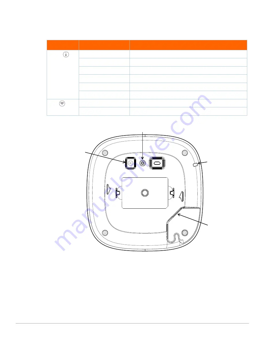
Figure 2  

AP22 Rear View

Ethernet Port

The AP22 is equipped with a 10/100/1000Base-T auto-sensing MDI/MDX Ethernet port (E0). This E0 port supports 

wired-network connectivity, and Power over Ethernet (PoE) from IEEE 802.3af and 802.3at compliant PoE power 

sources, such as a PoE midspan injector or a network switch.

Kensington Lock Slot

The AP22 access point is equipped with a Kensington lock slot for additional security.

Table 1  

AP22 Access Point LEDs Status

LED

Color/State

Meaning

System 

No Lights

Device has no power

Blinking


Green

Device is starting

Alternating Green/Amber

Device is ready for setup

Solid Green

Device is ready

Solid Amber

Device has detected a problem

Solid Red

Device has an issue- immediate action required

Radio

No Lights

Wi-Fi is not ready, wireless clients cannot connect

Solid Green 

Wi-Fi is ready, wireless clients can connect

E0

Reset Button

DC Power Socket

Kensington Lock Slot

Summary of Contents for Instant On AP22

Page 1: ...s services Package Contents 1 x AP22 access point 1 x Mount bracket 1 x Ethernet cable Hardware Overview Figure 1 AP22 Front View If you have ordered AP22 bundle the package would also include a power...

Page 2: ...span injector or a network switch Kensington Lock Slot The AP22 access point is equipped with a Kensington lock slot for additional security Table 1 AP22 Access Point LEDs Status LED Color State Meani...

Page 3: ...hile the reset button is being held down 3 Release the reset button on the access point after 15 seconds Power If PoE is not available a proprietary Aruba power adapter can be used to power the AP22 a...

Page 4: ...ting ducts Make sure that access points are placed below ducts to avoid RF disturbances RF interference sources include Microwave ovens and other 2 4 or 5 GHz objects such as cordless phones Cordless...

Page 5: ...the mount bracket at an angle of approximately 30 degrees to the tabs see Figure 4 3 Twist the mount bracket clockwise until it snaps into place in the tabs see Figure 4 Figure 4 Attaching the Mount...

Page 6: ...g Rail Installing the Access Point to a Solid Surface 1 Attach the mount bracket to any solid surface such as a wall or hard ceiling as shown in Figure 7 a Install any necessary wall anchors Wall anch...

Page 7: ...tach the access point to the secured mount bracket as shown in Figure 8 a Align the access point with the mount bracket placing the access point so that it s mounting tabs are at an angle of approxima...

Page 8: ...rubaInstantOn com in the address bar to access the Aruba Instant On portal login screen In the login screen enter your Instant On account credentials to access your site Figure 9 Instant On Portal Log...

Page 9: ...ceiver Connect the equipment to an outlet on a circuit different from that to which the receiver is connected Consult the dealer or an experienced radio or TV technician for help Industry Canada This...

Page 10: ...tes 1 ce p riph rique ne doit pas provoquer d interf rences et 2 ce p riph rique doit accepter toute interf rence y compris les interf rences susceptibles de provoquer un dysfonctionnement En cas d ut...

Page 11: ...n no deseada Morocco This device is intended for indoor use in professional healthcare facilities This device has no IEC EN60601 1 2 essential performance Use of this equipment adjacent to or stacked...

Page 12: ...1 2 3 MPE 1 mW cm2 0 18mW cm2 Ukraine Hereby Hewlett Packard Enterprise Company declares that the radio equipment type APIN0505 is in compliance with Ukrainian Technical Regulation on Radio Equipment...

Page 13: ...ears following the date of the final distribution of this product version by Hewlett Packard Enterprise Company To obtain such source code send a check or money order in the amount of US 10 00 to Hewl...

Reviews: