background image

7.1.2. Patch points: Inputs vs. Outputs

The connectors in the MiniBrute 2 patch bay fall into two main categories: inputs and

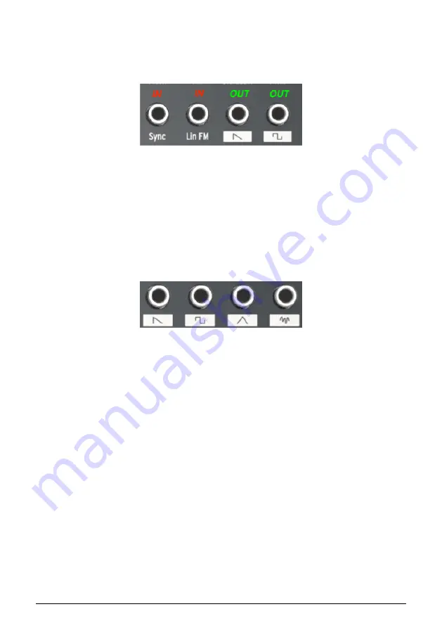
outputs. It is easy to know which is which: The output jacks are labeled with white boxes

containing text or graphics, and the input jacks only have words under them.

Use the output jacks as sources for the input jacks, and use the input jacks as destinations

for the output jacks.

7.1.3. Outputs are full-scale

The signal at the output jacks is the direct output of whatever source they represent. For

example, the waveform output jacks in the VCO 1 section are full-strength; adjusting the

sliders in the OSC MIXER section will not control their output levels.

Other examples include the Out 1 and Out 2 jacks in the LFO 1&2 section. If the direct output

signal of an LFO is too wide for the desired input destination, it will need to be limited

somehow. Fortunately, we have provided two sets of Attenuators in the patch bay for this

purpose. We'll describe how to use the

Attenuators [p.71]

in that section of the manual.

The input and output jacks have different

label types

Direct waveform outputs

Arturia - User Manual MiniBrute 2 - The Patch bay

54

Summary of Contents for minibrute 2 series

Page 1: ...USER MANUAL...

Page 2: ...Braakman Tom Hall Reek Havok Randy Lee Simon Gallifet ARTURIA SA 2017 All rights reserved 11 Chemin de la Dhuy 38240 Meylan FRANCE www arturia com Information contained in this manual is subject to c...

Page 3: ...d to be correct at the time of printing However Arturia reserves the right to change or modify any of the specifications without notice or obligation to update the hardware that has been purchased IMP...

Page 4: ...tches the input voltage specified on the AC power adapter 9 Do not open and insert anything into the instrument as this could cause a fire or electrical shock 10 Do not spill any kind of liquid onto t...

Page 5: ...atch bay This physical matrix allows you to route modulation sources in a nearly endless number of ways both within the MiniBrute 2 and with external devices Couple these features with the sheer music...

Page 6: ...7 Legato vs Retrigger note response 40 5 8 The Patch bay section 40 5 9 Secondary Shift functions 40 6 Basics of synthesis 41 6 1 Analog synthesizer architecture 41 7 The Patch bay 53 7 1 General con...

Page 7: ...mories 110 12 3 Local Templates 111 12 4 Store To Recall From 112 12 5 Import Export Device Settings 113 12 6 Data entry 114 12 7 Device Settings 115 13 Shift functions 123 13 1 SHIFT Keys 1 5 123 13...

Page 8: ...o sophisticated DSP algorithms the time was right for Arturia to introduce an analog synth of its own But reproducing analog circuitry is not the same as designing great sounding analog circuits so we...

Page 9: ...rld and patch them into the MiniBrute 2 circuitry This open ended approach to sound design will open sonic doors you never knew were there We think it will even make the big boys come knocking at the...

Page 10: ...Two envelopes ADSR filter and AD amplitude Loopable AD envelope Two multi waveform LFOs with free run or sync modes Brute Factor overdrive the filter input with the audio output External audio can be...

Page 11: ...n on your power requirements This product should be used only with the components supplied or recommended by Arturia When used with any components please observe all safety markings and instructions t...

Page 12: ...jack 470 impedance line level Headphones 6 35 mm 1 4 TRS jack signal is mono 2 impedance 185mW 250 60mW 80 24mW 32 Patch bay most jacks 3 5 mm 1 8 miniature mono jacks CV inputs Eurorack level signals...

Page 13: ...of the connections that can be made between the MiniBrute 2 and external devices The possibilities are as endless as your imagination The MiniBrute 2 rear panel MiniBrute 2 patch bay modular synth an...

Page 14: ...he warm up period Once the synthesizer has reached its running temperature tune it to pitch Use an external tuner to check the instrument s tuning if needed adjust the Global Tune knob to tune the Min...

Page 15: ...nter position Set the VCO 2 Wave p 22 and Range p 29 switches to their up positions Sine wave and Fine Set the FILTER section s Mode knob to LP Set the AD ENVELOPE switches to the Gate p 39 and Once p...

Page 16: ...AT And like the Modulation Wheel it can introduce vibrato to the note you re holding This is a great way to add expressiveness to your playing 3 3 Add a second oscillator Press the Up Octave button t...

Page 17: ...in an electronic organ sound that has no dynamics By changing the AD ENVELOPE parameters Attack Decay we can control how the sound fades in and fades out Raise the AD ENVELOPE section s Attack slider...

Page 18: ...ins when the attack stage reaches its maximum value and determines the time it takes to decrease from this maximum value down to a steady level set by the sustain parameter see next The speed of this...

Page 19: ...LTER section in the patch bay Connect the other end of the patch cable to the Cutoff jack in the FILTER section It s important that everything is set up properly so here s how the patch should look Pl...

Page 20: ...he Sync button Before you can make music with the Sequencer or the Arpeggiator it is important to have the Sync button set to Int Internal Look at the right side of the MiniBrute 2 for a large button...

Page 21: ...00 If you haven t already done it press the large Sync button until the INT LED is lit Now press the Play button If the sequence is silent skip to the next section If it is not silent change the Seq...

Page 22: ...eters Transposition allows shifting the keyboard s note range over six octaves The pitch bend wheel allows adding real time pitch changes like bending strings on a guitar The modulation wheel allows a...

Page 23: ...nt of shift is proportional to the rotation of the wheel with its full range adjustable between one semitone to one octave by the Bend Range knob 4 2 2 2 Modulation wheel The second wheel is the Modul...

Page 24: ...attention to the blue letters that are silkscreened in various areas of the Control section for example look under the Octave buttons across the top of the keyboard and under the Transport section bu...

Page 25: ...cept control voltage signals from devices like a modular synthesizer or a MIDI controller e g a MIDI drum pad or wind controller or even audio signals from an external sound source such as a microphon...

Page 26: ...als is dependent on the Sync p 85 setting 4 5 4 USB Connect a standard type B USB cable to the USB port to interface with a computer Clock control and note data can be sent and received The reception...

Page 27: ...LFO 1 and 2 are identical so this section of the manual applies equally to both 5 1 1 Wave The LFOs offer several types of modulation waveforms The selection is made by the Wave knob sine triangle sa...

Page 28: ...the knob blinks in time with the rate Note that the LFO rate may be superseded by the Sequencer Arpeggiator tempo clock if the Sync switch is set to Seq see above When set to Sync the LFO rate will al...

Page 29: ...ach LFO that lets you decide if you want an LFO to retrigger when a new note is played To toggle this function hold the Shift button and then press the top F key LFO 1 or the top F key LFO 2 The LFO r...

Page 30: ...he knob counter clockwise to lower the pitch and rotate the knob clockwise to raise the pitch Changing the Fine Tune knob of VCO 1 does not affect the pitch of VCO 2 5 2 2 Glide Glide is also known as...

Page 31: ...e frequency pitch of VCO 1 as the value of this knob is increased When range switch of VCO 2 is set to LFO the frequency modulation will sound more like vibrato But when it is set to Fine or All the f...

Page 32: ...ob sets the modulation range for the Metalizer knob Velocity is routed to the Metal Mod by default but the patch bay allows you to use something else to modulate the parameter instead 27 Arturia User...

Page 33: ...y Modulation But there is an input on the patch bay that allows the VCO 1 pitch to be modulated by another source The output level of the second oscillator is controlled with the slider labeled Osc 2...

Page 34: ...enter frequency All a full turn of the knob will sweep VCO2 through the entire frequency range of the MiniBrute 2 LFO VCO2 can be used as an additional LFO with a wide frequency range 1Hz to audio ran...

Page 35: ...he filter s cutoff frequency The frequency range goes from below 20Hz when turned fully counter clockwise up to 18kHz when fully clockwise For example in LP mode you can adjust a sound s brightness As...

Page 36: ...iddle position 12 o clock no envelope modulation occurs When turned counter clockwise below the center the FM knob sends an increasing amount of the inverted ADSR envelope When turned clockwise above...

Page 37: ...ders to 0 Set the filter mode to LP Set the Cutoff knob to the 10 00 position Set the Resonance knob to the middle position 12 00 Set the LFO 1 waveshape to Sawtooth and the Rate to the 10 00 position...

Page 38: ...lation source The Att 1 portion of the label stands for Attenuator 1 The patch bay has a section labeled Attenuators and when a different source is routed to the first pair of connectors there that in...

Page 39: ...s distortion to the sound For low Brute Factor settings the distortion is smooth and gentle but it becomes more harsh as you turn up the knob When turned up higher than about 75 of the way the MiniBru...

Page 40: ...the amplitude at a constant level so you can program a sound with both hands To create a drone patch that is constantly evolving as parameters are being modulated via the patch bay To create a patch...

Page 41: ...ntly phase shifted using LFO 2 by default The phase shift of one copy is modulated at a constant rate 1Hz while the second copy s phase shift modulation rate can be controlled with the LFO 2 Rate knob...

Page 42: ...the Metal Amt source 5 6 4 Noise The signal mixer also provides the control of other signals which aren t generated by the oscillators The Noise slider potentiometer adjusts the amount of white noise...

Page 43: ...plifier by default Their functions have been described extensively here p 12 but here s a quick review The Attack slider sets the duration of the envelope s first stage The Attack time ranges from 1ms...

Page 44: ...AD Envelope is normally triggered when the ADSR Envelope is triggered but a different trigger source may be routed into the AD Envelope via the patch bay 5 6 9 2 Once Loop This switch toggles the fun...

Page 45: ...from their Attack stages unless a cable is plugged into one of the Trig inputs in the patch bay To toggle between Legato and Retrigger response hold the Shift button and press the highest E on the key...

Page 46: ...y which determines its pitch For example a pattern that repeats every 2 27ms corresponds to a fundamental frequency of 440 cycles per second or 440 Hertz a unit of measurement for cycles per second na...

Page 47: ...the signal s amplitude is always changing randomly Therefore it has no fundamental frequency hence no pitch and its harmonic spectrum consists of a nearly infinite number of frequencies that have no...

Page 48: ...dulator or PWM takes the square wave and changes the ratio between the time the waveform is at maximum or minimum The square wave corresponds to a 50 PW The pulse width can be set over a wide range 50...

Page 49: ...The top of a triangle wave is folded over by the Metalizer Arturia User Manual MiniBrute 2 Basics of synthesis 44...

Page 50: ...e signal or signals This can involve either attenuating filtering out or emphasizing resonating particular overtones and partials and these changes can be either static or dynamic Filters are very imp...

Page 51: ...ss mode because it passes the low frequencies below the cutoff and reduces the high frequencies above the cutoff This correlation of attenuation to frequency determines the filter s slope which is mea...

Page 52: ...other controllers creates dynamically changing interesting timbres 6 1 3 3 Resonance or emphasis Resonance is a filter s ability to amplify or emphasize partials that are close to the cutoff frequenc...

Page 53: ...in is controllable through various modulation sources such as an LFO envelope generator or some kind of external control like a foot pedal The amplifier is primarily responsible for shaping a sound s...

Page 54: ...lators are the LFO low frequency oscillator and envelope generator but they can also be provided by external sources that generate control voltage CV signals that provide modulation and gate signals t...

Page 55: ...inimum In the OSC MIXER section Lower the Osc 2 slider to minimum Lower the Osc 1 square wave slider to minimum Raise the Osc 1 sawtooth slider to maximum The sawtooth wave has more harmonic content t...

Page 56: ...unt of time it will take for the filter to die out after releasing the note Raise the AD Decay slider to about 3 4 of the way up Set the ADSR Decay and Sustain sliders to about 2 3 of the way up Play...

Page 57: ...verview of the patch at this point just to make sure we re on the same page When you play a note the sound should start quickly and brightly and die just as quickly when the note is released While the...

Page 58: ...thesizers that can generate compatible signals 7 1 General concepts 7 1 1 Patch bay sections A white line is drawn around certain groupings of input output jacks This indicates which connections are r...

Page 59: ...of whatever source they represent For example the waveform output jacks in the VCO 1 section are full strength adjusting the sliders in the OSC MIXER section will not control their output levels Othe...

Page 60: ...tch bay But to use one example from the section pictured above the label KBD means the Pitch of VCO 1 normally tracks the MiniBrute 2 keyboard abbreviated KBD If a patch cable is connected to the VCO...

Page 61: ...ronized to an external clock source Likewise the Sync output jack is intended to transmit signals to an external device so that the MiniBrute 2 can serve as the master clock source for an external dev...

Page 62: ...ection s Att 2 input the pre wired control is the internal 5V source of the MiniBrute 2 But you can patch any control voltage standard into the patch bay here 1V 2V 5V 8V etc These labels indicate int...

Page 63: ...at connection with a patch cable allows the new source to control the phase shift modulation rate of the second copy of the sawtooth wave Remember the amount of the Ultrasaw modulation is governed by...

Page 64: ...which is a technical term that means that slow LFOs or envelopes are not likely to be wavefolded properly by the Metal In circuitry 7 2 6 Metal Mod The default source of the Metal Mod parameter is the...

Page 65: ...set FM and RM to center 12 00 Set Cutoff and Resonance to zero and Att 1 Cutoff to 2 00 Set the ADSR Attack and Release to zero Set the ADSR Decay and Sustain about 2 3 of the way up Make the followin...

Page 66: ...d listen to the pitch of VCO 1 Turn the VCO 1 FM knob gradually from zero to about the 4 00 position Result After the FM knob passes the 12 00 point the original pitch of VCO 1 becomes increasingly di...

Page 67: ...raise the FM knob in the VCO 1 section As you do the fundamental pitch of VCO 1 will change as it did earlier in this example Changing the tuning of VCO 2 will provide a lot of interesting sounds thr...

Page 68: ...generator The setting of the Noise slider in the OSC MIXER has no effect on this connector To control its level route it through one of the Attenuator p 71 pairs 7 3 The VCO 2 section 7 3 1 Pitch 2 in...

Page 69: ...at the Ext slider passes through the Filter section and is processed by the Amplifier section It could be any sort of audio signal another synth a microphone or a musical passage Whatever it is it wil...

Page 70: ...knob must be set to a non zero value 7 5 2 RM input LFO 1 is routed to the Resonance Modulation parameter by default but when another source is plugged into this jack it will become the modulation so...

Page 71: ...thing with LFO 1 but you want the sawtooth wave to ramp upward instead of downward here s what to do Set the LFO 1 Wave to Sawtooth Connect a cable to the Out 1 jack of the LFO 1 2 section in the patc...

Page 72: ...pen plug the new source into the ADSR Trig input jack 7 8 2 ADSR Out jack The ADSR Envelope is a flexible modulator If you want to use its stages to control an internal parameter e g VCO 1 FM connect...

Page 73: ...from the new source into this patch point 7 9 3 AD Decay The Decay time of the AD Envelope can be modulated by an external source instead of by the Decay slider in the AD ENVELOPE section The source...

Page 74: ...veform To control its level route it through one of the Attenuator p 71 pairs 7 10 2 LFO Out 2 This jack provides the full strength output of the selected LFO 2 waveform To control its level route it...

Page 75: ...te input jack if you like But their main function is to provide access to the patch bay for incoming control signals 7 11 1 In 1 In 2 In 1 and In 2 are identical in function so we will cover them both...

Page 76: ...by plugging in one side of a patch cable to the appropriate input jack You could also use a dummy TS plug if you prefer to avoid cable clutter In practical terms using the same example if you want to...

Page 77: ...you want to control into the In 2 jack and then use the Out 2 Amp jack as the source for the desired destination parameter To control the level of the modulation use the Att 2 Amp knob in the AMP sec...

Page 78: ...n until the LED next to the word CLK is lit Use the MIDI Control Center p 109 to instruct the MiniBrute 2 what sort of external clock is being used as the sync reference 1step Gate 1step Clock 1pulse...

Page 79: ...and another Arturia product such as the MatrixBrute the BeatStep Pro or the KeyStep These products send and receive their Sync and Start signals from a single jack Simply connect one TRS patch cable...

Page 80: ...CLK and connect the second TS cable from the Run Reset output of the master device to the Reset input jack of the MiniBrute 2 Be sure to match the clock rates between the two devices You can specify t...

Page 81: ...enuators so you can adjust the modulation amount to fit the desired note range 7 14 2 Gate The Gate jack sends an on off trigger when a note is played The gate will stay open as long as the note is he...

Page 82: ...switch is set to Wheel the Mod wheel will control the destination parameter If it is set to Aftertouch then the pressure sensitivity of the keyboard will be the modulation source instead When using th...

Page 83: ...tch When this switch is set to Seq a sequence can be played or recorded Use the other controls in this section to select the active sequence and the time division at which the sequence will play back...

Page 84: ...IDI Control Center p 109 chapter 8 2 3 Tap Rest The Tap button allows you to set the tempo of the active sequence or arpeggio on the fly All you have to do is tap it in time with the music The number...

Page 85: ...Control Center to make changes All three buttons are active in sequencer mode while only the Play Pause and Stop buttons are used with the arpeggiator Each button has a secondary Shift function when...

Page 86: ...hift and press the appropriate key to make a selection When creating a sequence it is also possible to enter a value of Tie which holds a note into the following step See the Tie notes p 90 section of...

Page 87: ...e first note of a pair longer and the second note shorter Assuming the time division is set to 1 8 here s what will happen With Swing set to Off 50 each note gets equal time resulting in a straight 1...

Page 88: ...amount is set to 75 in each case Technically the description of what happens is If a smaller resolution is selected the swing period will be subdivided in 2 n trigs of equal length Maybe the followin...

Page 89: ...s Time Division MiniBrute 2 is able to jump over one or more Time Division values without having them affect the rhythm of your sequence or arpeggio So if you d like to switch Time Div from 1 4 to 1 1...

Page 90: ...LK Clock They will configure the MiniBrute 2 to work with many different types of devices and systems 8 8 1 As Master MiniBrute 2 is the master clock when the INT option is selected When this is the c...

Page 91: ...and USB outputs 8 8 2 1 Sync In Out types The MIDI Control Center can be used to configure the MiniBrute 2 to send and receive one of the following types of clock signals at the Sync input and output...

Page 92: ...1 Basic Operation 9 1 1 Select and play a sequence The sequencer will not run if the Sync p 85 selection is set to something other than INT and no external clock is present 9 1 1 1 Seq Arp toggle swi...

Page 93: ...her by holding the Shift button and pressing the appropriate Octave shift button Oct or Oct 9 2 1 Transpose When this mode is active you can use the keys to transpose a sequence while it is running To...

Page 94: ...ou have to do to create a sequence is Press the Record button Note the next step will erase the existing sequence Play a series of notes one key at a time When you re done press the Stop button You mu...

Page 95: ...lts could be something like this If you want the rest between two notes to be longer press the Tap button as many times as you need 9 3 1 2 Tie notes It s possible to make a note hold over into the ne...

Page 96: ...he legato phrase release the Tap Rest button Enter more notes as desired or press the Stop button to exit Record mode On a mono synth such as the MiniBrute 2 the process described above will result in...

Page 97: ...ess the Rec button and the same thing will happen MiniBrute 2 will begin recording and replacing notes If needed you can punch in and out of record mode by pressing the Record button repeatedly while...

Page 98: ...ce However if the Swing value is changed while the sequence is playing it is important to remember to press the Stop button before switching to another sequence or to the Arpeggiator Otherwise the cha...

Page 99: ...ult But there s an option in the MIDI Control Center p 109 to make sure every recorded note has the same velocity value You can also specify exactly what that value will be See the MIDI Control Center...

Page 100: ...e lengthened and A note that matches the previous step will be tied no new attack A new note that does not match the previous step will be legato To add a rest to the end of the sequence press the Tap...

Page 101: ...nter So be sure to back up your hard work to your computer often And once the sequences are safely stored on your computer it is possible to hand pick sets of sequences that are aimed at particular au...

Page 102: ...ator provides lots of different ways to arpeggiate the notes you play on the keyboard The following features were covered in the Shared Features p 78 chapter Setting the rate p 23 or tempo Time divisi...

Page 103: ...s the Play Pause button hold down some keys and the arpeggiator will start You can add up to 16 notes to an arpeggio we ll show you how in the Build a multi octave arpeggio p 103 section There is also...

Page 104: ...relative to the tempo quarter notes one step per beat eighth notes two steps per beat and so on Triplet values are offered as well 1 4T 1 8T etc 10 3 6 Hold mode To activate Hold mode press the Shift...

Page 105: ...der from the bottom to the top When it reaches the top it will start again from the bottom The results will sound something like this 10 4 2 Arp mode Down With the Arp mode encoder set to Dwn the arpe...

Page 106: ...re will not a predictable pattern so it is possible that a note could be repeated one or more times before a new note is heard 10 4 6 Arp Mode Order With the Arp mode encoder set to Order the arpeggia...

Page 107: ...it will play each note twice before the next note plays 10 4 8 Arp Mode Down x2 With the Arp mode encoder set to Dwn x2 the arpeggiator will play the held notes in order from the top to the bottom But...

Page 108: ...to start the arpeggiator Activate the Hold function hold Shift press the Tap Rest button Keep at least one key down at all times until the final step Press one or more keys the arpeggio will play thos...

Page 109: ...iliar with how the pattern sounds press Play Pause in the middle of the pattern The pattern will pause Press Play Pause again The pattern will resume and continue playing normally Keep in mind the arp...

Page 110: ...learn how to access the manual click here p 108 This chapter will cover only the MIDI Control Center features that are unique to the MiniBrute 2 11 1 2 System requirements PC 2 GB RAM CPU 2 GHz Windo...

Page 111: ...indows OS The MIDI driver for the MiniBrute 2 is not multi client That s a technical term that simply means this If a DAW application is already active on your computer the MIDI Control Center will no...

Page 112: ...and type in the letters AMS If you do not see the MIDI Studio window hold the Command key and press 2 Turn the unit off or disconnect its USB cable You should see the related device icon turn grey Se...

Page 113: ...n to the MIDI Control Center describing each section of the software window and defining important terms you will need to know while using the MIDI Control Center such as the Browser and Template The...

Page 114: ...The User Templates are the ones you have recalled from your MiniBrute 2 with the MCC See the Store To Recall From p 112 section to learn how to do this A Template contains the 8 patterns from Sequenc...

Page 115: ...window contains a location called the Working Memory It functions as a sort of target onto which a group of sequences i e Templates can be dragged and then transmitted to the MiniBrute 2 internal memo...

Page 116: ...your computer in this way You can also send a Template into the MiniBrute 2 internal memory using the Store To button See the Store To Recall From p 112 section for more instructions about these proce...

Page 117: ...tore all eight sequences from the selected Template into the MiniBrute 2 12 4 2 Recall edited sequences from MiniBrute 2 If you changed any sequences inside the MiniBrute 2 you need to pull those sequ...

Page 118: ...Device Settings Use these files to share settings and sequences with other users 12 5 Import Export Device Settings Immediately under the Device Settings tab are two buttons labeled Import and Export...

Page 119: ...a field To edit the Fixed Velocity Value for example click and drag the knob graphic or double click in the value field and enter a new value To edit a parameter such as the Tempo Knob Mode click its...

Page 120: ...User Fixed follow User channel Keyb Velo curve Log Lin AntiLog Personalized response Keyb Aftertouch curve Log Lin AntiLog Personalized response Keyb MIDI Out Port USB and or MIDI Send to MIDI USB or...

Page 121: ...a mod wheel is assigned to MIDI CC 1 But this parameter allows you to set it to a different MIDI CC number so you can use it as an alternate modulation source 12 7 1 6 Pitch Bend MIDI Ch This determin...

Page 122: ...of the Tempo knob Two settings are available Jump The tempo value will respond immediately when the Rate knob is turned Hook The tempo will not change until the Rate knob passes through the current v...

Page 123: ...enable velocity sensitivity Fixed Velocity Value 0 127 Set the preferred value Tap Tempo 2 3 or 4 taps Number of taps to respond LFO1 Key Retrig Disable Enable LFO will run freely or retrigger when a...

Page 124: ...middle somewhere Wait to Load MiniBrute 2 will not change sequences until the end of the current sequence Instant Change The sequence changes immediately and starts at the top of the new sequence If t...

Page 125: ...nces can be transposed by external devices This decides which ones are allowed to do so Transpose Input channel 1 16 all Specifies the MIDI channel to obey for transposition Transpose Center Pitch Ful...

Page 126: ...than one note is played on the keyboard at the same time this parameter determines whether the pitch will be derived from the highest or lowest note played This also affects the KBD output at the KBD...

Page 127: ...hine Control commands MMC or both 12 7 5 2 Stop Record Play You can define the MIDI channel and CC number for each of the three main Transport commands independently All three must transmit the same t...

Page 128: ...coder p 125 Wait to change time division changes after SHIFT is released 13 1 SHIFT Keys 1 5 Use this combination to select one of the 5 Gate p 76 settings Sequencer mode and Arpeggiator mode have ind...

Page 129: ...xisting sequence which makes the sequence longer 13 9 SHIFT Seq encoder Also known as Skip Seq Arp Modes p 84 Instructs the Sequencer and the Arpeggiator not to change the current sequence or arpeggia...

Page 130: ...the Sequencer and the Arpeggiator not to change the Time Division until the Shift button is released This makes it possible to select non adjacent Time Division settings without having to pass through...

Page 131: ...n all the installations If this product is found to be the source of interferences witch can be determined by turning the unit OFF and ON please try to eliminate the problem by using one of the follow...

Reviews: