7
Doc.-no.: DPC310_01_EN Issue: 01/2018
START UP
4.
Start up
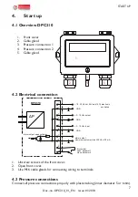
4.1 Overview DPC310
1. Front cover
2. Cable gland
3. Pressure connection 1
4. Pressure connection 2
5. Cable gland
1.
2.
3.
4.
5.
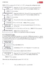
4.2 Electrical connection
Potentialfreier Kontakt
offen:
Sollwert 1
geschlossen: Sollwert 2
+ 10...30 Vdc oder 24 Vac (±15%) Versorgung
- GND
+ 0...10 Vdc Ausgang
- GND
Alarm Ausgang
hochohmig: Alarm aus
niederohmig: Alarm an
maximaler externer Stromkreis: 30 Vdc / 30 mA
1
2
3
4
5
6
7
8
9
10
ΔP
DPC310
Alarm Ausgang: Open Collector
Elektrischer Anschluss
+ 0...10 Vdc Eingang
- GND
dry contact
open: Setpoint 1
close: Setpoint 2
+ 10...30 Vdc or 24 Vac (±15%) electronic
excitation
- GND
+ 0...10 Vdc output
- GND
alarm output
maximum customer circuit 30 Vdc / 30 mA
1
2
3
4
5
6
7
8
9
10
ΔP
DPC310
alarm output: open collector
+ 0...10 Vdc input
- GND
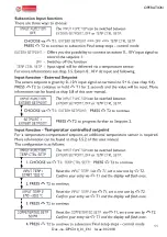
1. Unscrew screws of the front cover.
2. Open front cover.
3. Use M16 cable glands for connecting wiring to terminals.
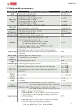
4.3 Pressure connections
Connect all pressure connections properly with plastic tubing (inner diameter 5 or 6mm).

