


15
Doc.-no.: DPC310_01_EN Issue: 01/2018
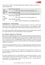
The alarm delay time can also be set in the menu.
Alarm ON:
Alarm OFF:
Alarm ON
= low resitance,
Alarm OFF
= high resistance
Output voltage steadily greater than: 0.95 • maxU
out
for set alarm delay time
Output voltage steadily less than: 0.9 • maxU
out
for set alarm delay time
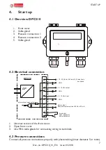
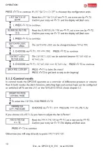
5.4.2 Measuring mode:
For limit value monitoring, a limit value can be entered under the menu item “limit switch”.
The previously set parameters are taken into account (unit, measured variable, k-factor and
the measuring range). In the basic state, the limit values are not active, and the menu item
“limit switch” shows “OFF” in the second line.
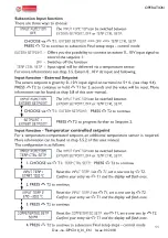
Three menu items, which influence the switching behavior of the open collector output,
follow the „limit switch“ menu item:
1. “alarm delay time” with this menu item the switching delay time can be set. The setting
range is 1...60 s or 2...15 min. In the basic state, this value is set to 10 seconds
2. “switching logic” here you have the possibility to set the limit values to MAX or MIN. At
MAX, an alarm is triggered, when the measured value exceeds the limit value; at MIN, the
alarm is triggered when the limit value is exceeded.
3. “Contact logic” the rest state or the switching state of the open collector output can be
set differently. “Active high” means that when an alarm occurs, the open collector output
becomes low-impedance. “Active low” means that the alarm switches the open collector
output high-impedance
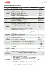
The following switching pattern can be summarized:
switching
logic
contact
logic
pressure
alarm output
display
MAX
active
high
ΔP > limit value
alarm ON, low resistance
!
ΔP <
limit value alarm OFF, high resistance
MAX
active
low
ΔP > limit value
alarm ON, high resistance
!
ΔP <
limit value alarm OFF, low resistance
MIN
active
high
ΔP > limit value
alarm OFF, high resistance
ΔP <
limit value alarm ON, low resistance
!
MIN
active
low
ΔP > limit value
alarm OFF, low resistance
ΔP <
limit value alarm ON, high resistance
!


