i
User ’s Guide • O.P.E.S. Electrosurgical Generator
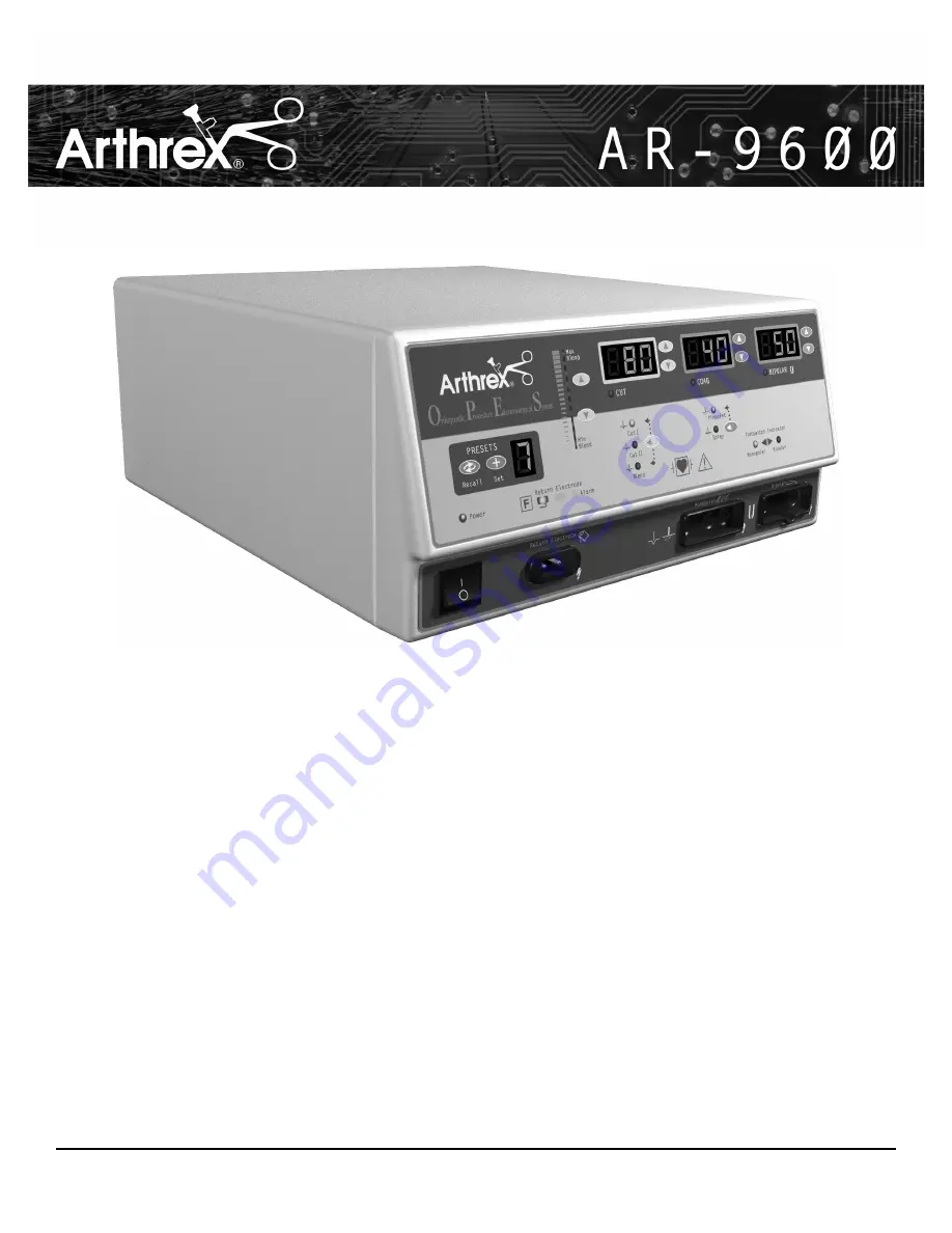
O.P.E.S
ORTHOPAEDIC PROCEDURE ELECTROSURGICAL SYSTEM
USER’S GUIDE
Page 1: ...i User s Guide O P E S Electrosurgical Generator O P E S ORTHOPAEDIC PROCEDURE ELECTROSURGICAL SYSTEM USER S GUIDE ...
Page 2: ...hone 239 643 5553 www arthrex com Arthrex GmbH Liebigstrasse 13 D 85757 Karlsfeld München Germany Phone 49 8131 59570 Fax 49 8131 5957631 Arthrex S A S 5 Avenue Pierre et Marie Curie 559260 Lezennes France Phone 33 3 20057272 Fax 33 3 20057270 Arthrex Ltd Beehive Works Milton Street Sheffield South Yorkshire S3 7 WL England Phone 44 114 276 7788 Fax 44 114 276 7744 Arthrex GesmbH Triesterstrasse 1...
Page 3: ... not reported within 7 days of receiving the product the warranty could be rendered void We also refer to our general terms of business CONVENTIONS USED IN THIS GUIDE WARNING Indicates a potentially hazardous situation which if not avoided could result in death or serious injury CAUTION Indicates a hazardous situation which if not avoided may result in minor or moderate injury NOTICE Indicates an ...
Page 4: ...n Checks 3 2 Setting Up the Unit 3 2 Checking the Return Electrode Alarm 3 2 Confirming Modes 3 3 Checking Bipolar Mode with bipolar footswitch 3 3 Checking Monopolar Mode with monopolar footswitch 3 3 Checking Monopolar Mode with handswitch 3 3 Performance Checks 3 3 Using the Arthrex O P E S Electrosurgical Generator 4 1 Inspecting the Generator and Accessories 4 2 Setup Safety 4 2 Setting Up 4 ...
Page 5: ... A 2 Dimensions and Weight A 2 Operating Parameters A 2 Transport and Storage A 2 Audio Volume A 3 Return Electrode Sensing A 3 Low Frequency 50 60 Hz Leakage Current A 3 High Frequency RF Leakage Current A 4 Standards and IEC Classifications A 4 Class I Equipment IEC 60601 1 A 4 Type CF Equipment IEC 60601 1 Defibrillator Proof A 4 Drip Proof IEC 60601 2 2 A 4 Electromagnetic Interference A 4 Ele...
Page 6: ...e unit power switch and front panel receptacles 2 9 Figure 2 8 Layout of connectors and controls on the rear panel 2 10 Figure 5 1 Fuse holder 5 2 Figure A 1 Output power vs impedance for Cut I mode A 5 Figure A 2 Output power vs impedance for Cut II mode A 5 Figure A 3 Output power versus impedance for Blend mode set at Minimum A 6 Figure A 4 Output power versus impedance for Blend mode set at Ma...
Page 7: ...ludes the following information Key Features Components and Accessories Safety CAUTIONS Read all warnings cautions and instructions provided with this generator before using Read the instructions warnings and cautions provided with electrosurgical accessories before using Specific instructions are not included in this manual ...
Page 8: ...ion of 10 factory set presets can be reset to your preferred settings Refer to the Preset table in Section 4 of this guide Two levels of coagulation Pinpoint and Spray Pinpoint provides precise control of bleeding in localized areas Spray provides greater control of bleeding in highly vascular tissue over broad surface areas Return electrode sensing and contact quality monitoring The Arthrex O P E...
Page 9: ...ctionality This feature eliminates the need for non hand controlled devices Digital vs analog The use of digital technology improves the sensing rate used by the generator compared to other electrosurgical generators on the market today COMPONENTS AND ACCESSORIES You should receive the following components with your generator Arthrex O P E S Electrosurgical Generator Hospital grade power cord 110 ...
Page 10: ...t is for use only by trained licensed physicians Danger Fire Explosion Hazard Do not use the Arthrex O P E S Electrosurgical Generator in the presence of flammable materials Fire Explosion Hazard The following substances will contribute to increased fire and explosion hazards in the operating room Flammable substances such as alcohol based skin prepping agents and tinctures Naturally occurring fla...
Page 11: ...pecific procedure being undertaken Use by physicians without such training has resulted in serious unintended patient injury including bowel perforation and unintended irreversible tissue necrosis For surgical procedures where the high frequency current could flow through parts of the body having a relatively small cross sectional area the use of bipolar techniques may be desirable to avoid unwant...
Page 12: ...al procedures Inadvertent electrosurgical burns may result To avoid the possibility of an electrosurgical burn to either the patient or the physicians do not allow the patient to come in contact with a grounded metal object during activation When activating the unit do not allow direct skin contact between the patient and the physician Remove any loose fitting jewelry from the patient before activ...
Page 13: ...2 1 User s Guide O P E S Electrosurgical Generator CONTROLS INDICATORS AND RECEPTACLES This section describes The Front and Rear Panels Controls Indicators Receptacles and Ports ...
Page 14: ...FRONT PANEL Figure 2 1 Layout of controls indicators and receptacles on the front panel 2 2 Arthrex Inc ...
Page 15: ...eturn Electrode Solid Return Electrode Regulatory Symbology Read instructions before use Defibrillator Proof Type CF Equipment RF Isolated patient connections are isolated from earth at high frequency Power Switch and Handpiece Connectors Return Electrode Receptacle Caution High Voltage Cut Mode Coag Mode Monopolar Handpiece Receptacle Bipolar Mode Bipolar Handpiece Receptacle Preset Controls Reca...
Page 16: ...s not one of the user defined presets Set Button Sets the desired preset into one of the 10 user defined presets Press and hold the Set button for three seconds to save the settings Recall Button Toggles through the 10 presets Stop at the desired number 0 9 illumi nated in the Preset Number Display to recall a Preset Preset Number Display Indicates the current selection of one of the 10 presets 0 ...
Page 17: ...n Cut or Blend mode is activated Cut and Blend Mode Selector Toggles between Cut I Cut II and Blend modes Blend Amount Indicator Indicates the amount of blend added in the Blend mode More bars illuminated indicates more blend divided into 10 steps Blend Amount Control Buttons Increases or decreases the amount of blend Level 1 10 added in the Blend mode Cut I Mode Indicator Indicates when the Cut I...
Page 18: ...reases or decreases the Pinpoint or Spray Coag power output in increments of 1 to 10 watts Coag Activation Indicator Illuminates when Coag mode is activated Pinpoint and Spray Mode Selector Toggles between Pinpoint mode and Spray mode Pinpoint Mode Indicator Indicates when the Pinpoint mode is selected Spray Mode Indicator Indicates when the Spray mode is selected ...
Page 19: ...rator Bipolar Power Display watts Indicates the power set for the Bipolar mode Displays error code in the event of an error Bipolar Power Control Buttons Increases or decreases the Bipolar power output in increments of 1 to 10 watts Bipolar Activation Indicator Illuminates when Bipolar mode is activated ...
Page 20: ...lectrode alarm condition Solid Return Electrode Indicator Illuminates when the system detects a solid return electrode Split Return Electrode Indicator Illuminates when the system detects a split return electrode Monopolar Footswitch Indicator Illuminates when monopolar footswitch control is plugged in and available Bipolar Footswitch Indicator Illuminates when bipolar footswitch control is plugge...
Page 21: ...trosurgical Generator Power On Off Switch Turns the unit on or off Bipolar Receptacle Accepts standard cables for bipolar handpieces Connect bipolar accessories Return Electrode Receptacle Accepts a standard return electrode plug Monopolar Handswitching Receptacle Accepts standard 3 pin handpieces Connect handswitching accessories ...
Page 22: ... Rear Panel 2 10 Arthrex Inc SYMBOLS DESCRIPTION Equipotential Ground Stud Non ionizing Radiation Volume Control Danger Explosion Risk If Used With Flammable Anesthetics Fuse Enclosed Relay Connector Monopolar Footswitch Input Jack Bipolar Footswitch Input Jack Read Instructions Before Use ...
Page 23: ...3 1 User s Guide O P E S Electrosurgical Generator GETTING STARTED This section includes the following information Initial Inspection Installation Function Checks Performance Checks ...
Page 24: ... the location of connectors and controls WARNING At no time should you touch the active electrode or bipolar forceps A burn could result Setting Up the Unit 1 Verify that the Power Switch is in the Off O position and that no accessories are connected to the unit 2 Connect a hospital grade power cable to the AC power cable receptacle on the back of the unit then to a properly grounded wall outlet 3...
Page 25: ...e Cut activation tone 4 While activating the Cut mode rotate the volume control over the full range to verify that the sound is audible throughout the range 5 Press the Coag pedal blue on the footswitch Verify that the Coag mode activation indicator illuminates and that the system generates the Coag activation tone 6 While activating the Coag mode rotate the volume control over the full range to v...
Page 26: ...3 4 Arthrex Inc ...
Page 27: ...s and Factory Settings Setup Safety Blend Controls Setting Up Activating the Unit Preparing for Monopolar Surgery Activation Safety Preparing for Bipolar Surgery CAUTIONS Read all warnings cautions and instructions provided with this generator before use Read the instructions warnings and cautions provided with electrosurgical accessories before use Specific instructions are not included in this m...
Page 28: ...training has resulted in serious unintended patient injury including bowel perforation and unintended irreversible tissue necrosis For surgical procedures where the high frequency current could flow through parts of the body having a relatively small cross sectional area the use of bipolar techniques may be desirable to avoid unwanted coagulation If the patient has an implantable cardioverter defi...
Page 29: ...s are recommended For details refer to the procedures for your institution or to local codes Provide at least 10 to 15 cm 4 to 6 in of space from the sides and top of the generator for cooling Normally the top sides and rear panel are warm when you use the generator continuously for extended periods of time 3 Plug the generator power cord into the AC Power Cable Receptacle on the rear panel 4 Plug...
Page 30: ...unt of hemostasis Level 1 10 Adjustment is preformed by pressing the up or down buttons next to the Blend setting indicator Select the desired power settings for Cutting Adjustment is preformed by pressing the up or down buttons next to the Cut display When the light above Cut I illuminates a low Cut mode is selected When the light above Cut II illuminates a pure Cut mode is selected Select the mo...
Page 31: ...g activation During activation the activated mode can be adjusted up and or down a maximum of four steps Refer to the following table for power increments While operating the unit outside of a user defined preset small red dot will be blinking in lower right corner of the Preset display as an indicator the unit temporarily stores the power setting for the activated mode Cut Coag or Bipolar This te...
Page 32: ...gical Generator incorporates 10 factory set presets that can be reset to your preferred settings Follow the in Setting and Recalling Memory Presets to set your user defined presets The following table shows the preset factory settings NOTICE Presets only store one Cut mode Cut I or Cut II or Blend and power setting one Blend level if applicable one Coag mode and power setting and Bipolar power set...
Page 33: ...ing describes how to adjust the Blend setting Ascending illuminated bars indicate increased hemostasis Increase and decrease the amount of blend added to the Blend mode by pressing the Blend amount control buttons NOTICE There are 10 levels of blend available in the Blend mode When selecting the Blend mode the unit defaults to a setting of minimum blend only the first bar is illuminated 4 7 User s...
Page 34: ...edure using Preset 2 same as Example 1 Preset values He changes the settings by selecting the Cut II mode The displayed power will remain at 30 watts The physician then adjusts the power to 100 watts He resumes the procedure now using Cut II at 100 watts He then switches the mode back to Cut I The power output returns to 30 watts as stored in the 2 Preset The physician switches again to the Cut II...
Page 35: ...sence of flammable anesthetics Fire Explosion Hazard The following substances will contribute to increased fire and explosion hazards in the operating room Flammable substances such as alcohol based skin prepping agents and tinctures Naturally occurring flammable gases that may accumulate in body cavities such as the bowel Oxygen enriched atmospheres Oxidizing agents such as nitrous oxide N2O atmo...
Page 36: ...e patient before activation Studies have shown that smoke generated during electrosurgical procedures can be potentially harmful to patients and the surgical team These studies recommend adequately ventilating the smoke by using a surgical smoke evacuator or other means 1 Examine all accessories and connections to the electrosurgical generator before use Ensure that the accessories function as int...
Page 37: ...5 1 User s Guide O P E S Electrosurgical Generator MAINTAINING THE ARTHREX O P E S ELECTROSURGICAL GENERATOR This section covers the following topics Cleaning Periodic Inspection Fuse Replacement ...
Page 38: ...he generator PERIODIC INSPECTION Every six months visually inspect the Arthrex O P E S Electrosurgical Generator for signs of wear or damage In particular look for any of the following problems Damage to the power cord Damage to the power cable receptacle Obvious damage to the unit Damage to any receptacle Accumulation of lint or debris in or around the unit FUSE REPLACEMENT Fuses for the unit res...
Page 39: ...6 1 User s Guide O P E S Electrosurgical Generator TROUBLESHOOTING This section includes Error Code Descriptions and actions to take to resolve them ...
Page 40: ...whichever mode is activated by the surgeon first will be the function dispensed by the generator Examples of this functionality would include A When the handpiece Cut button is pressed the generator is activated for Cut If the handpiece Coag button is then pressed while still depressing the Cut button the generator will continue to deliver Cut power If the Cut Button is released prior to releasing...
Page 41: ...7 1 User s Guide O P E S Electrosurgical Generator REPAIR POLICY AND PROCEDURES Refer to this section for information on Responsibility of the Manufacturer Returning the Generator for Service ...
Page 42: ... Telephone number fax number Type of repair to be done Department address city state and zip code P O number Model number Step 2 Clean the Generator WARNING Electric Shock Hazard Always turn off and unplug the generator before cleaning NOTICE Do not clean the generator with abrasive cleaning or disinfectant compounds solvents or other materials that could scratch the panels or damage the generator...
Page 43: ...al Generator TECHNICAL SPECIFICATIONS All specifications are nominal and subject to change without notice A specification referred to as typical is within 20 of a stated value at room temperature 25 C 77 F and a nominal input power voltage ...
Page 44: ...evice should be stored and used in a room temperature of approximately 770 F 250 C A 2 Arthrex Inc Ambient temperature range 34 to 65 C 29 to 149 F Relative humidity 0 to 75 non condensing Atmospheric pressure 500 hPa to 1060 hPa Input Voltage 100 240 VAC Mains line frequency range nominal 50 60 Hz Power consumption 500 VA Fuses two 6 3 A slow blow Width 31 1 cm 12 25 in Depth 41 3 cm 16 25 in Hei...
Page 45: ...not adjustable 70 dB 5dB Frequency 2 kHz 1 2 seconds 1 kHz 1 2 seconds Duration 2 seconds Solid Trip resistance 0 Ω to 5 Ω 3 Ω Continuous measurement Once the system establishes the solid return electrode resistance an increase of 20 Ω 5 Ω in resistance will cause an alarm When the alarm condition exists the system deactivates output power Split Trip resistance 10 Ω 5 Ω to 135 Ω 10 Ω Continuous me...
Page 46: ...gnetic interference to video equipment used in the operating room Electromagnetic Compatibility IEC 60601 1 2 and IEC 60601 2 2 The Arthrex O P E S Electrosurgical Generator complies with the appropriate IEC 60601 1 2 and IEC 60601 2 2 specifications regarding electromagnetic compatibility Voltage Transients Emergency Generator Mains Transfer The Arthrex O P E S Electrosurgical Generator operates ...
Page 47: ...es that follow depict the changes for each mode at specific power settings Figure A 1 Output power vs impedance for Cut I mode Figure A 2 Output power vs impedance for Cut II mode A 5 User s Guide O P E S Electrosurgical Generator ...
Page 48: ...Figure A 3 Output power versus impedance for Blend mode set at Minimum Figure A 4 Output power versus impedance for Blend mode set at Maximum A 6 Arthrex Inc ...
Page 49: ...or Pinpoint mode Figure A 6 Output power vs impedance for Spray mode A 7 User s Guide O P E S Electrosurgical Generator Pinpoint Coag 0 20 40 60 80 100 120 140 0 500 1000 1500 2000 2500 3000 Load Resistance Ohms Output Power Watts 120W 60W ...
Page 50: ...Figure A 7 Output power vs impedance for Bipolar mode A 8 Arthrex Inc ...
Page 51: ...facturers defects in material and craftsmanship under normal use and service The warranty periods for Arthrex Inc products are as follows Electrosurgical Generators One year from date of shipment Mounting Fixtures all models One year from date of shipment Footswitches all models Ninety days from date of shipment Patient Return Electrodes Shelf life only as stated on packaging Sterile Single Use Ac...
Page 52: ...s discretion provide reasonable use of loaner Equipment while repair or replacement is underway This warranty applies only to the original Customer and is not transferable except at the discretion of Arthrex Repairs and replacements made under this warranty are not warranted beyond the remainder of the warranty period ARTHREX S LIABILITY SHALL BE LIMITED SOLELY AT ARTHREX S OPTION TO REPAIR OR REP...