DLC910 Function Module Installation and Operations Manual
11
Monitoring DLC910 Operations
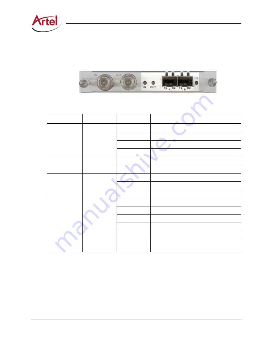
Understanding the Rear Panel Status LEDs
describes the states of the DLC910 rear panel status LEDs as shown in
Figure 7.
DLC910 Rear Panel Status LEDs
Input is enabled and valid video detected
Table 3.
DLC910 Rear Panel Status LEDs
LED
Indicates . . .
State
Description
IN
Input status
indicator
Off
Input is disabled.
Green
Input is enabled and valid video detected.
Yellow
Input is enabled but no input detected.
Red
Input is enabled but invalid format detected.
OUT
Transmit status
indicator
Off
Not enabled.
Green
Valid SDI signal output.
SFP A, B TX
SFP transmit
status
Off
No SFP installed.
Green
Normal operation.
Red
SFP TX fault.
SFP
A, B RX
SFP receive status
Off
No SFP installed.
Green
Input enabled and signal detected.
Yellow (flashing)
RX optical power high.
Red
Loss of signal.
Red (flashing)
RX fault or RX optical power low.
OK
Module status
--
Same operation as the front panel OK LED
(see
Using the Monitor Jack
The front panel MON (monitor) jack provides an additional copy of the DLC910 output. Pressing the Select
button scrolls through the full screen and four quadrant views. Pressing this button changes all DLC910
outputs and has the same function as changing the View Mode in DL Manager.
To connect a monitor the DLC910, connect the monitor cable between the monitor and the 75 Ohm HD-BNC
monitor jack located on the DLC910 front panel (see
Summary of Contents for DigiLink DLC910
Page 2: ...ii DLC910 Function Module Installation and Operations Manual...
Page 4: ...iv DLC910 Function Module Installation and Operations Manual...
Page 8: ...viii DLC910 Function Module Installation and Operations Manual...
Page 26: ...Index Index 2 DLC910 Function Module Installation and Operations Manual...
Page 27: ......


