background image

Page 46 · 5400 Series 

TECSource 

User’s Manual 


External Fan Control 


The 

TECSource

 has a built-in user adjustable 4-12V DC power supply designed 

to provide up to 350mA to an external fan, such as those built into the 

240 

Series


LaserMounts

. When using the 

TECSource

 with mounts that require a 

fan, no additional external power supply is needed, and the Arroyo 

126xB

 series 

cables all include the wiring to connect the fan power to the mount. 
 
Fan control is setup in the 

Fan Setup Menu

 using the 

Ext Fan, Ext Fan Pwr, Ext 

Fan Mode, 

and

 Ext Fan Off

 settings. 


Ext Fan 

can be set to 

Off

Slow

Medium

Fast

, or 

Custom

. When set to 

Off

, the 

fan power is never turned on. 

Slow

Medium

, and 

Fast

 correspond to 9V, 10.5V, 

and 12V. To select a different voltage, choose the 

Custom

 setting and then 

adjust the 

Ext Fan Pwr


Menu

 item to the desired voltage, from 4.0V to 12.0V. 

 
The fan on/off mode can be controlled using the 

Ext Fan Mode

 setting. There 

are five modes: 
 

Auto 

Fan is turned on whenever the TEC output is on, and turns off when the 

TEC output is turned off. 

On 

Fan is always on. 

Delay 

Similar to the 

Auto

 mode, the fan is turned on whenever the TEC output 

is on, but when the TEC is turned off, the fan will remaining running for 
an addition number of minutes as defined by the 

Ext Fan Off 

setting. 

Cool 

Fan is turned on whenever the TEC output is on and cooling, fan is off 
otherwise. 

Heat 

Fan is turned on whenever the TEC output is on and heating, fan is off 
otherwise. 


Summary of Contents for TECSource 5400 Series

Page 1: ......

Page 2: ...bility 31 Out Off Menu 32 Applying Sensor Limits 33 Working With Thermistors 34 Working With RTDs 35 2 Wire versus 4 Wire Measurements 36 Working With AD590s and LM335s 37 Gain Control and the PID Loo...

Page 3: ...is being changed and parameters are displayed in clear English no cryptic numbers or LEDs to decode The TECSource offers all the features you would expect from a modern temperature controller includin...

Page 4: ...noted by the WARNING heading explain dangers that could result in physical injury or death Cautions noted by the CAUTION heading explain conditions that could result in damage to the instrument other...

Page 5: ...onnel will void the warranty Please see the Service section later in this manual for instructions on how to obtain service for this instrument WARNING To avoid electrical shock ensure a 3 prong power...

Page 6: ...rmistor If the TECSource is being connected to a LaserMount no changes need to be made as this is the thermistor used in the mount However if you are using manufacturer s thermistor or a different Bet...

Page 7: ...straightforward as the quick start section above illustrated This section will provide additional details and considerations for installing your TECSource After unpacking the unit make sure all packin...

Page 8: ...several degrees higher than room ambient does not exceed the unit s operating temperature Warm up and Environmental Considerations In order to achieve the highest level of accuracy the TECSource shoul...

Page 9: ...emote Sense 4 Sensor 1 11 Sensor 1 Remote Sense 5 Sensor 3 AD590 12 Sensor 3 AD590 6 Sensor 2 13 Earth Ground 7 Fan 14 Sensor 2 15 Fan Signal Ground Output Connector 17W2 Female Inverting the TE Outpu...

Page 10: ...onal series resistance for lower current devices such as blue LEDs TEC On LED Circuit Diagram Auxiliary Connector The Auxiliary connector is a female DB 25 and has the following pin out Pin Descriptio...

Page 11: ...into any USB 1 1 or USB 2 0 port For more information on using the USB interface see the Computer Interfacing Manual which is included on the CD that accompanied this product RS232 Connector The RS232...

Page 12: ...ional safety and operational information Front Panel Operation Operation of the TECSource is very straightforward The sections below will help familiarize you with the front panel the display and the...

Page 13: ...d Yellow Remote Unit is being controlled via a computer Green Cool Instrument is cooling Green Heat Instrument is heating Green Stable Temperature is stable Green ITE Limit Controller is in current li...

Page 14: ...desired sensor value is known or when the sensor to temperature conversion values are not available for your sensor Main Display Screen The top of the main display will be the temperature of the acti...

Page 15: ...layed instead of the actual temperature In Ite Mode the actual temperature is displayed No Set Point Error Because the TECSource uses a digital PID loop it will always stabilize at the set point and y...

Page 16: ...are contained inside a sub menu such as communications settings To access the sub menu simply press the knob to enter the sub menu when its name is displayed Below is a complete list of available sett...

Page 17: ...temperature limit of the active sensor It is a duplicate of the active sensor T Lo Lim in the Sensor Limits menu copied here for ease of access 99 C T Hi Lim Only displayed when operating in T Ite Mod...

Page 18: ...einhart Hart equation for use with primary sensors 1 2 0 87755E 07 RTD A The A term in the RTD equation for use with primary sensors 1 2 3 98480E 03 RTD B The B term in the RTD equation for use with p...

Page 19: ...isabled Aux3 Sets the Auxiliary 3 temperature sensor type Disabled Aux4 Sets the Auxiliary 4 temperature sensor type Disabled ThermA The A term in the Steinhart Hart equation for use with auxiliary se...

Page 20: ...alog Out Menu Function Selects the output function of the Analog Output Disabled Analog Set When Function is set to Direct sets the output voltage of the Analog Out BNC 0 000V T Error When Function is...

Page 21: ...age from 4 0 to 12 0 volts See the External Fan Control section below for more information 12 0 Ext Fan Mode Controls when the fan operates See the External Fan Control section below for more informat...

Page 22: ...ows for restoring the instrument to defaults saving configurations and restoring configurations See Saving and Restoring Configurations below for more information No Change Brightness The vacuum flore...

Page 23: ...sor limit No Out of Tol Turns off the TEC output if the TEC is out of tolerance No ITE Limit Turns off the TEC output if the TEC hits the current limit No TEC Open Turns off the TEC output if the TEC...

Page 24: ...ECSource is being controlled by a computer over the USB or RS232 interfaces When in remote mode the TECSource behaves differently preventing you from affecting the operation of the instrument Some of...

Page 25: ...t s set point changed Saving and Restoring Configurations Using the System Menu Config menu item or the SAV and RCL commands over the computer interfaces TECSource allows you to save up to four config...

Page 26: ...PUT commands can be used to construct a script allowing you to configure the instrument change modes change set points turn outputs on or off or any other of a wide range of actions Script creation mu...

Page 27: ...nsor inputs primary and auxiliary The principle difference between the two is that only primary sensors can be used to control the temperature of your device or mount Auxiliary sensors can only be use...

Page 28: ...mperature limit By default auxiliary sensors that exceed their temperature limits will not cause the output to shut down If you want auxiliary sensors to cause temperature limit shutdowns set Out Off...

Page 29: ...y cases an LED can be directly connected across the digital output and ground Each digital output has an invert setting to reverse the state of the output if an active low signal is required These set...

Page 30: ...ntlk Err menu entry the interlock can be used to generate an error and shutdown the output if the interlock input is open Is Open or shorted If Closed The Interlock input is an electrically isolated i...

Page 31: ...t least 5 seconds Once this condition is met the Stable LED will light If at any time the actual temperature goes further away from the set point the instrument is no longer and will not start countin...

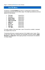
Page 32: ...Sensor Short default Yes Apply Nonactive default No Apply Aux default No R Limit default No Out of Tol default No ITE Limit default No TEC Open default Yes For each condition if the menu item is set...

Page 33: ...non active primary sensors when determining if a temperature limit condition exists When set to Yes non active primary sensors in limit will cause a temperature limit condition If No non active primar...

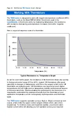
Page 34: ...s in temperature and this is the range in which most 10K thermistors are typically used 10K thermistors can be used at much higher temperatures but will suffer poorer temperature stability performance...

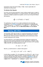
Page 35: ...RTDs also function by converting temperature into resistance but unlike thermistors RTDs increase in resistance as temperature increases RTDs are also a fairly linear device meaning they can be used a...

Page 36: ...measurement mode that uses separate sensor and source lines to remotely sense the actual resistance of the RTD and eliminate the cable or connector resistances When using 4 wire measurement mode only...

Page 37: ...or LM335 is T MTC B Where TC is the temperature in C calculated using the standard conversion value of 1 C A or 0 1 C mV as appropriate and adjusted from Kelvin to Celsius LM335 is only supported by s...

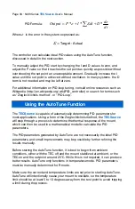
Page 38: ...e of automatically determining PID parameters for most applications Using a form of the Ziegler Nichols method the TECSource will step through a process to determine the thermal response of the mount...

Page 39: ...ill remain on and the display will show AutoTune Successful The three PID parameters will also be displayed Due to display limitations only the first 2 places of resolution is displayed but additional...

Page 40: ...never started an AutoTune process since the last power up Turning the output off remotely will cancel the AutoTune process and generate an E 436 error More details on the use of the command can be fo...

Page 41: ...ng the step size Note that changing the step size will not change the resolution of the displayed value for either the set point or the actual temperature Resistive Heaters and Heat Cool Only Modes Th...

Page 42: ...mposed limit which means that the response time to over limit conditions can be several hundred milliseconds During that response time a significant over voltage condition can persist However with a p...

Page 43: ...sistance is to short the TE and TE connections making sure whatever you are using to short the terminals is not itself adding resistance to the circuit and is rated for the current you intend to use a...

Page 44: ...ged or simply monitored as a process variable The voltage can be controlled using one of the following functions as set in the Analog Out Func menu item Direct with this function the analog output vol...

Page 45: ...l the transfer function of temperature to output voltage T Range is in C V The output function looks like this For example if the actual temperature was 25 4 C and T Range was set to 10 C V then the a...

Page 46: ...fan power is never turned on Slow Medium and Fast correspond to 9V 10 5V and 12V To select a different voltage choose the Custom setting and then adjust the Ext Fan Pwr Menu item to the desired voltag...

Page 47: ...CAL GET Retrieves user calibration settings TEC USERCAL RESET Resets all user calibration settings to factory defaults To prevent accidental modification of the calibration settings the entries are on...

Page 48: ...in some configurations When driving a low voltage load at higher currents a condition can arise where the voltage of the load is too low and unaddressed would result in excessive heat inside the inst...

Page 49: ...imum voltage requirements for the standard 5400 15 28 5400 30 28 and 5400 20 56 TECSource controllers Custom configurations will have a different profile 0 4 8 12 16 20 24 28 0 5 10 15 TEC Voltage Vol...

Page 50: ...28 TECSource Example At 25A the minimum voltage at the TEC connector must be greater than 8V Anything less and the instrument will lower the current to stay above the red line Operating Zone Any combi...

Page 51: ...ion mA 10 Accuracy reading mA 0 30 0 60 0 30 Voltage Resolution mV 10 Accuracy reading V 0 0 05 Sensor6 10 A Thermistor Range k 0 1 450 Resolution k 0 01 Primary Accuracy read k 0 05 50 Aux Accuracy r...

Page 52: ...Range 20 192 Resolution 0 01 Accuracy reading 0 03 0 1 Current Limit Resolution A 0 1 Accuracy A 0 2 Other Fan Supply 4 12V 350mA max Relay Limits 30VDC 1A max TEC Connector Female 17W2 Display Type...

Page 53: ...ct the factory for assistance E 007 Preset EEPROM Failed The preset settings section of the EEPROM which contains user section defaults is corrupted The corruption cannot be repaired automatically ple...

Page 54: ...ts in the selected slot the slot number is out of range or if the configuration is corrupted E 218 Configuration Save failed An attempt to save a configuration failed This can be caused if the slot nu...

Page 55: ...libration failure The calibration process failed due to improper setup an interfering action set point change output on off or unexpected results E 419 TEC not stable The TEC exceeded the stability li...

Page 56: ...turned outputs off Notification message only A user configuration was recalled from memory while the outputs were on resulting in the outputs being turned off W 806 No function key assigned Notificati...

Page 57: ...ervice for support Service Service and repair for the TECSource can be obtained by contacting the distributor from where you purchased the instrument or directly from Arroyo Instruments A complete lis...

Page 58: ...lity Repairs will be made and the instrument returned freight prepaid Repaired products are warranted for the balance of the original warranty period or 90 days whichever first occurs Limitation of Wa...

Page 59: ...0 4 4 2012 Electrical Fast Transients Burst 1kV AC 0 5kV I O EN61000 4 5 2014 Surges 0 5kV differential mode 1kV common mode EN61000 4 6 2013 Conducted Immunity 3V EN61000 4 11 2004 Supply Dips ad Var...

Page 60: ...Page 60 5400 Series TECSource User s Manual Copyright 2016 Arroyo Instruments All Rights Reserved P N 530 1039 Rev D...

Reviews: