


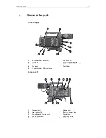


Camera Layout
17
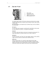
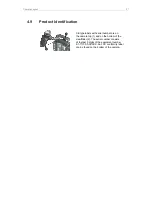
4.4
Media Panel
1
2
3
4
5
1
Media Lid
2
Card Status LEDs
3
CFast Card Slots A & B
4
USB Connectors 1 & 2
5
Ethernet Connector
Card Status LEDs
The card status LEDs allow for a quick check of the card status:
Status LED
Card State
Off
No card inserted
Green
Ready to record
Flashing red
Recording
Solid red
Not ready to record, card full or card invalid
CFast Card Slots A & B
Storage media slots for CFast 2.0 recording cards.
USB Connectors 1 & 2
Interface for USB memory sticks with FAT file system. The camera
saves data such as user setups, frame grabs and system logs to the
USB memory sticks. The USB ports can also be used to charge USB
devices and supplies 5V with a maximum current of 500mA.
Ethernet Connector
RJ45 LAN interface for remote control of the camera, for multicam
control and for service access.


