- 75 -
C
ONNECTION OF THE REMOTE MAINTENANCE BYPASS
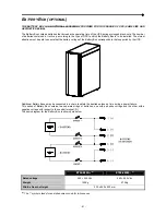
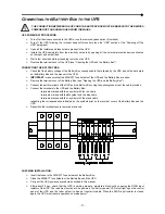
An additional maintenance bypass can be installed on a peripheral electric control panel, for example to replace the UPS
without interrupting power to the load.
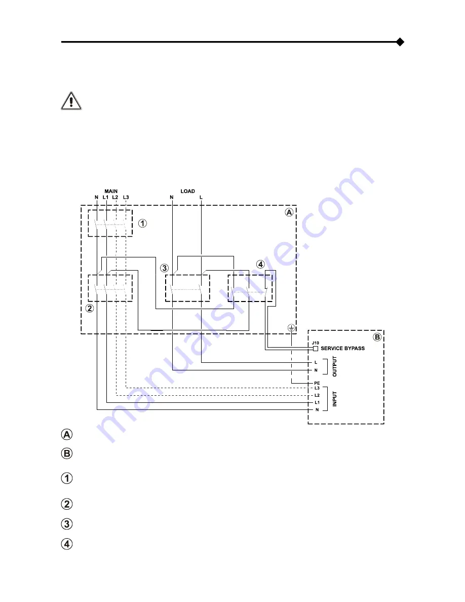
It is essential to connect the SERVICE BYPASS terminal (
see "View of UPS connections", point 2) to
the auxiliary contact of the SERVICE BYPASS switch. Closing the SERVICE BYPASS switch (4), will
open this auxiliary contact which signals the insertion of the maintenance bypass to the UPS.
Absence
of this connection could interrupt the power to the load and cause damage to the UPS.
NOTE: use cables with a cross-section compliant with the indications given in the “Cable Sizes” section.
Use
1mm
2
cables with double isolation to connect the SERVICE BYPASS terminal to the auxiliary contact of
the remote maintenance bypass disconnecting switch.
If the UPS is fitted with an internal isolation transformer, ensure compatibility between the remote
maintenance bypass and the neutral arrangements.
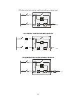
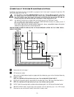
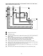
DIAGRAM SHOWING REMOTE INSTALLATION OF THE MAINTENANCE BYPASS ON THE THREE PHASE –
SINGLE PHASE MODEL
Peripheral electric control panel
UPS internal connections
LINE switch:
magneto-thermal switch compliant with the indications given in the “External Protection
Devices” section.
NOTE: For installation with single phase input, use a bi-polar
magneto-thermal switch
.
INPUT switch: disconnecting switch compliant with the indications given in the “UPS Internal Protections” section.
NOTE: For installation with single phase input, use a bi-polar disconnecting switch.
OUTPUT switch: disconnecting switch compliant with the indications given in the “UPS Internal Protections” section.
SERVICE BYPASS switch: disconnecting switch compliant with the indications given in the “UPS Internal
Protections” section, complete with auxiliary contact that is normally closed.
Summary of Contents for Flexus FM
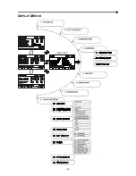
Page 33: ...84 DISPLAY MENUS...

