Armstrong Steam QM-3 Calibration Manual Download Page 4

Armstrong International
IOM-246-V2.0
Steam QM-3 Calibration

Page 2 of 14


Safety 

Icon Legend

Burn hazard! Uninsulated components upstream of cabinet may be hot.

• 

Do not touch when unit is working.

• 

Allow to cool before moving or servicing unit.

Live steam will cause burns; condensate water may cause them. Skin exposure 

to 140 °F (60 °C) water for only five seconds may cause a second degree burn.

This device must be installed in accordance with appropriate local, 

national, and international standards, codes, and practices.

Read this manual. It contains important information.

Service must be performed by a qualified person.

Installation should always be accompanied by competent 

technical assistance.

Improper installation, start-up, operation, maintenance, or service 

may void warranty.

You are encouraged to contact Armstrong International or its local 

sales representative for additional information.

Shock hazard! High voltages present inside equipment.

• 

Electrical installation must be performed by qualified personnel.

• 

Disconnect power before performing any electrical service.

Equipment must be disposed of according to applicable 

environmental requirements.
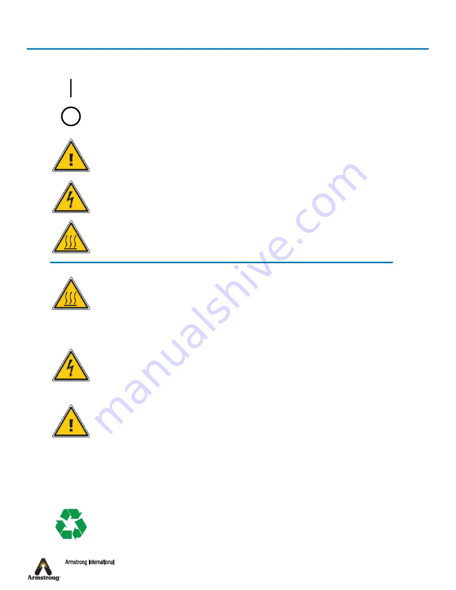
Indicates Power On

Indicates Power Off

Indicates important information concerning potential 

for personal injury or damage to equipment

Indicates electrical hazard

Indicates hot surface

Keep unit away from heat-sensitive equipment and installations.

Summary of Contents for Steam QM-3

Page 1: ...auts Sarts 2 me avenue 4 4040 HERSTAL BELGIUM T l 32 0 4 240 90 90 Fax 32 0 4 240 40 33 armstronginternational com Keep this manual with equipment for future reference STEAM QM 3 Steam Quality Monitor...

Page 2: ...ginternational com Armstrong Contents Revision History 1 Safety 2 Abbreviations and Acronyms 3 General Information 4 Recalibration Procedure 6 Calibrating the Temperature Sensors 6 Calibrating the Pre...

Page 3: ...librated Page 6 Recalibration Procedure Section Point 3 has been added Remove the Temperature Sensor T1 after unplugging it and plug it back in before install it in oil bath Calibrating the Temperatur...

Page 4: ...ualified person Installation should always be accompanied by competent technical assistance Improper installation start up operation maintenance or service may void warranty You are encouraged to cont...

Page 5: ...seconds DIN Deutsches Institut f r Normung eV dP Differential Pressure EC European Community EEC European Electrotechnical Commission EN European Norm EV Electronic Valve F Fahrenheit gal Gallon h Hou...

Page 6: ...nsors in the oil bath and recreate the actual temperatures for calibration This method is not covered in this document Pressure transmitter The pressure sensor is calibrated by simulating the voltage...

Page 7: ...ibrated on the Steam QM 3 The instruments are 3 temperature sensors 1 pressure transmitter 1 heating element 1 condensate flow meter 1 gas flow meter NCG meter 2 differential pressure sensors Heating...

Page 8: ...4 If not you must adjust the sensor 11 On the Steam QM 3 display pad press left and right arrows simultaneously to access the code menu 12 Enter 234 using the up and down arrows to change numbers and...

Page 9: ...edure in step 1 for T3 Temperature sensor NOTE Any corrections to the calibration certificate must be done following good documentation practices The error is crossed through by a single line The corr...

Page 10: ...the Steam QM 3 display pad press up and down arrows simultaneously to access the Debug sensor menu 7 Write the value of P1 on the calibration certificate If P1 is 0 1 bar regarding the set point 0 bar...

Page 11: ...d press left and right arrows simultaneously to access the code menu 7 To access the resistance calibration menu enter 069 using the up and down arrows to change numbers and the left and right arrows...

Page 12: ...alve from the draw vessel slowly to establish a cycle rate of the EV2 valve of approximately 30 seconds One cycle is from opening to closure of valve you should be able to hear this If the environment...

Page 13: ...ertificate NOTE Any corrections to the calibration certificate must be done following good documentation practices The error is crossed through by a single line The correction is written alongside wit...

Page 14: ...r syringe before resetting to 2ml 8 With the NCG injector syringe disconnected reset the syringe to 2ml 9 Connect the NCG injector syringe to the middle of the NCG injector assembly tee with a 6mm tub...

Page 15: ...w sensor calibration menu 24 On the Steam QM 3 display pad press left and right arrows simultaneously to access the code menu 25 To access the flow sensor calibration menu enter code 123 using the up...

Page 16: ...er draw vessel connecting to the bottom of the NCG burette use two wrenches 10mm and 11mm to ensure no damage to the NCG burette occurs Reconnect the expansion coil to the bottom of the NCG burette us...

Reviews: