2
5. CREATING ARCS
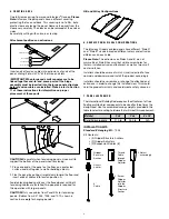
Carefully remove wrap from around Infusions
®
Canopy.
Please
Note:
Infusions Graphix panels have a different covering
protecting the face and back. This covering is not a film, but a
plastic sleeve enclosing the panel. Remove the panel from the
sleeve very carefully. The sleeve can be removed at the ends or
sides
by carefully cutting with scissors or tearing.
Attachment positions on extrusions
Center Access
Tensioning
Suspension
Accessories
A
B
C
D
Extrusion Slot Identification
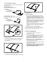
Insert ends of tension cables into extrusions at ends of the
panel, sliding it into slot “A” of the three end slots.
I
MPORTANT: When large and small canopies are to be
linked together end-to-end, some parts of the hinge
assembly must be inserted into the large panel extrusions
before tension cables are installed. Please refer to Section
11 of these instructions for information on proper
placement of these parts.
Insert Tension Cable
A
1
2
3
CAUTION:
Be careful when tensioning panels. Use a wall to
support the bottom of the panel when tensioning.
1. Place one end of the panel on the floor, on a protected
surface, and butt against a wall or building column.
2. Flex the panel by pulling straight down toward the floor and
insert ends of cables into tension position A.
Avoid extending body parts over the flexed panel until both
tensioning cables are installed. Two people are required for
this operation with larger panels.
CAUTION:
Only use cables from Panel Kits for tensioning
panels. (Cables from Kit 7004, 7005, and 7010, shown in
section 6, are
only
for hanging panels.)
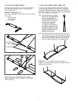
Hill and Valley Configurations
Hill and Valley Configurations
6. GRAPHIX PANEL VISUAL CONSIDERATIONS
The Infusions Graphix printed panels have different “Side A”
and “Side B” visuals based on different colors and extrusion
differences on each side.
Please Note:
The extrusions on Sides A and B are not
symmetrical. Side B has small but visible screw holes for
factory-installed extrusion attachment as well as two small
center notches.
Installers should be aware of which visual is desired to face
upward and downward and install the product accordingly.
Installers should never remove or change the attached end
extrusions in order to change this installed view. This would
void the product warranty and could create safety concerns.
7. PANEL SUSPENSION
The International Building Code requires the attachment of free
floating architectural components to be sized for three times the
design load. Use the assembled canopy weights provided in this
table to select mounting hardware that will meet this requirement:
Material
2' x 5'
2' x 6'
4' x 10'
Solid Polycarbonate
21.0 lb
25.0 lb
N/A
INSTALLATION KITS
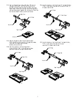
Standard 8' Hanging Kit
– 7004
Kit Contents:
• (2) Gripper Structure Anchors
• (2) Gripper Adjusters
• (2) Suspension Cables (8')
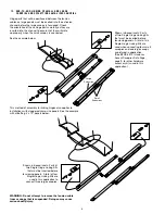
Gripper
Structure
Anchor
Gripper
Adjuster
8'
Cable
3. Adjust
accordingly
1. Thread
Cable
through
Gripper
Adjuste
r
2. Screw
Gripper
Adjuster
into the
Gripper
Structure
Anchor


