background image

                                                                              26

                                                        Pictures for illustrating purposes only             


Series EHU-750  steam humidifier in 3 X 220V - 50/60 Hz  


EHU-750 

Steam production  

(Kg/h) 

In 

Imaxi 

Pmaxi 

 Cylinder size 

Steam  

Torroidal 

( A ) 

( A ) 

( KW ) 

diameter 

transformer 

wiring 

752-5 

10 

10,9 

4,2 

Small 

25 

Straight through 

752-8 

15,8 

17 

6,5 

Small 

25 

 Straight through 

752-10 

10 

19,7 

21,1 

8,1 

Small 

25 

Straight through 

753-15 

15 

29,6 

31,6 

12 

1 x Large 

40 

Split 

753-20 

20 

39,4 

41,9 

16 

1 x Large 

40 

Split 

753-25 

25 

49 

52 

19,8 

1 x Large 

40 

Split 

754-30 

32 

64,9 

68,7 

26,2 

2 x Large 

40 

Split 

754-40 

40 

78,9 

83,5 

31,8 

2 x Large 

40 

Split 

755-50 

50 

99 

104,6 

39,9 

3 x Large 

40 

Split 

755-60 

60 

119 

125,7 

47,9 

3 x Large 

40 

Split 

755-70 

70 

138 

145,7 

55,5 

3 x Large 

40 

Split 

ALL WORKS CONCERNED WITH ELECTRICAL INSTALLATION MUST BE CARRIED OUT BY A SKILLED AND QUALIFIED PERSONNEL 

Series EHU-750 steam humidifier in 3 X 230V - 50/60 Hz   


EHU-750 

Steam production  

(Kg/h) 

In 

Imaxi 

Pmaxi 

 Cylinder size 

Steam  

Torroidal 

( A ) 

( A ) 

( KW ) 

diameter 

transformer 

wiring 

752-5 

9,6 

10,5 

4,13 

Small 

25 

Straight through 

752-8 

15,3 

16,5 

6,49 

Small 

25 

Straight through 

752-10 

10 

19,1 

20,5 

8,07 

Small 

25 

Straight through 

753-15 

15 

28,7 

30,6 

12,04 

1 x Large 

40 

Split 

753-20 

20 

38,2 

40,6 

15,98 

1 x Large 

40 

 Split 

753-25 

25 

47,8 

50,7 

19,95 

1 x Large 

40 

Split 

754-30 

32 

62,9 

66,6 

26,21 

2 x Large 

40 

Split 

754-40 

40 

76,5 

81 

31,84 

2 x Large 

40 

 Split 

755-50 

50 

95,6 

101,1 

39,75 

3 x Large 

40 

Split 

755-60 

60 

114,7 

121,2 

47,66 

3 x Large 

40 

Split 

755-70 

70 

133,8 

141,3 

55,57 

3 x Large 

40 

Split 

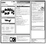
SERIES EHU-750 HUMIDIFIER 

Installation - Step 5


Summary of Contents for EHU-750 Series

Page 1: ...Pictures for illustrating purposes only SERIES EHU 750 HUMIDIFIER 752 753 754 755 Technical manual ...

Page 2: ...sitioning 14 to 21 Step 3 Optional temperature control system 22 Step 4 Condensate outlet 23 Step 5 Electrical connections 24 to 39 Step 6 Control connection 40 Setting up 41 System management Humidifier status menu 42 44 Humidifier configuration menu 45 Configuration changing menu 46 48 Maintenance Cylinder maintenance guide 49 Precaution 50 Service alerts 51 to 53 Main board changing 54 Steam cy...

Page 3: ...ring operation and therefore surfaces and pipe work become very hot Ensure that equipment not sustaining high temperatures be kept away Warning the end user should ensure that the equipment be disposed of according to the local prevailing regulations Delivery and storage Any loss or damage during delivery should be reported to carrier by registered letter within 3 working days and be advised to Ar...

Page 4: ...ms or direct air humidification ANY OTHER APPLICATION IS NOT CONSIDERED USE FOR THE INTENDED PURPOSE THE MANUFACTURER CANNOT BE MADE LIABLE FOR ANY DAMAGE RESULTING FROM INCORRECT USE Water Series EHU 750 humidifiers are designed to be used with mains demineralized R O or softened water On no account attempt to introduce any other fluid or chemical into the system Water supply should not exceed 6 ...

Page 5: ... to conducted disturbances induced by radio frequency fields EN 61000 4 4 Electrical fast transient burnt immunity test EN 61000 4 5 Surge immunity test EN 61000 4 2 Electrostatic discharge immunity test EN 60204 1 Safety of machinery Electrical Equipment of machines Part 1 General requirements EN 292 Parts 1 2 Safety of machinery basic principle mechanical design Manufacturer s Name and Address A...

Page 6: ...s EHU 750 steam humidifier is manufactured in compliance with the European regulations 2002 95 EU RoHS This guideline regulates after July 1st 2006 the use of mercury cadmium lead soldering processes chrome VI as well as PBB and PBDE EHU 750 steam humidifiers manufactured previously to this date may contain above materials Name MINFRAY Jean Marie Position R D Engineer Date 05 06 2008 Signature ...

Page 7: ...ses SERIES EHU 750 HUMIDIFIER Delivery contents 1 Any loss or damage during delivery should be reported to carrier by registered letter within 3 working days and be advised to Armstrong or to authorized dealer It is recommended that the EHU 750 humidifier be kept in its transit packaging for as long as possible prior to maintenance If the humidifier is to be put into storage prior to installation ...

Page 8: ... in Kg Humidifier Water inlet Steam outlet Steam outlet spacing Drain outlet Drain outlet spacing Empty Opera ting Model A B C D E F G H EHU 752 1 SMCYL 475 540 217 215 355 355 15 23 EHU 753 1 LG CYL 550 680 272 270 410 410 22 37 EHU 754 2 LG CYL 845 680 272 270 400 300 400 300 30 60 EHU 755 3 LG CYL 1075 680 272 270 380 275 380 275 45 90 EHU 752 1 small cyl EHU 754 2 cylinders EHU 755 3 cylinders...

Page 9: ...m 5 On off rocker switch 6 Stand by lamp 7 Grommet 8 Drain cup upper 9 Water inlet valve 10 LCD display board 11 Remote information board option 12 Power contactor 13 Main circuit board 14 Filling cup 15 Drain valve 16 Cylinder strainer 17 Steam cylinder 18 Stainless steel electrode plate 19 High water level electrode 20 High water level electrode cable 21 Electrode live power cable 22 Cylinder wa...

Page 10: ...he installation of the humidifier and the steam water and electrical networks For further technical assistance feel free to call Armstrong Failure to adhere to manufacturer s installation recommendations will invalidate your warranty Steps Setp 1 Placing and wall attachment Step 2 Water connection Step 3 Steam pipe positioning Step 4 Condensate outlet Step 5 Electrical connection Step 6 Control co...

Page 11: ...Armstrong humidifiers have been developped to be hanged on wall Before installation make sure that the surface material is strong enough to hold the humidifier The best performances of the humidifier are achieved when the steam discharge is made at short distance from the humidifier see after page n 20 Consider free space around the humidifier to allow easy access for maintenance purposes s a here...

Page 12: ...od Mark and drill the mounting holes for 6 mm screws s a the drilling distance table EHU 752 753 754 with 1 or 2 cylinders 4 mounting screws EHU 755 with 3 cylinders 5 mounting screws Insert pegs in holes and the upper screws Allow about 10 mm for hanging the cabinet Hang the cabinet and level it vertically and horizontally Screw up the upper screws and then screw up the lower screws Detail of han...

Page 13: ...ached after one or two days when using low conductivity waters This period can be shortened by adding a tea spoon of salt that has been firstly diluted in 1 4 litre of water Pour the mixture into the filling cup Caution do not touch the water Risk of electric shock THIS MUST BE CARRIED OUT BY A SKILLED AND QUALIFIED PERSONNEL No chemical agent whatsoever chlorine disinfectant ozone must be added t...

Page 14: ...s possible There are two steam inlet diameters available Ø 25 mm and Ø 40 mm STEAM DISTRIBUTION PIPE Steam distribution pipe selection table The number of distribution pipes and the diameters depend on the humidifier model SM CYL small cylinder LG CYL large cylinder To get the best steam distribution select the longest possible distribution pipe to fit the duct Standard distribution pipes are avai...

Page 15: ...n To prevent condensation this evaporation distance should be calculated before positioning the steam distribution pipe How to calculate the evaporation distance D In order to determine the evaporation distance the attached calculation table can be used HR1 relative humidity of air before humidification in HR2 relative humidity of air after humidification in D minimum humidification distance in me...

Page 16: ...r in case the level of humidity exceeds the preset value In case the recommended distances cannot be met please contact Armstrong or their authorized agent for an alternative solution If accurate values cannot be reached a distance of 2 m should be considered as a minimum distance between pipes obstruction and 3 4 m before sensor or humidistat A humidity sensor located near the steam pipe will cau...

Page 17: ...llowing dimensions and spaces according to your configuration For further information please contact Armstrong or their authorized agent H1 110mm Minimum height between the duct floor and the axle of the steam pipe H2 140mm Minimum distance between two pipes H3 160mm Minimum height between the duct top and the axle of the steam pipe The H3 distance can be 80 mm at the shortest in case the steam pi...

Page 18: ...3 0 à 4 5 1 H3 In duct with limited height the distribution pipe s can be tilted by 30 to get the 80 mm minimum height D Humidification distance d Duct diameter EXPRESSPACK The Armstrong ExpressPack is a bespoke steam humidification system made to suit your your configuration and ready to install in a ventilation duct It permits to have vapor trails evaporation distance as short as 600 mm For furt...

Page 19: ...team pipe should be attached to the duct with a threaded rod of Ø 5 mm going from the dedicated hole of the fixing plate to the outside of the duct and attached by a couple of nuts method 1 A rail attached to the inner side of the duct can also be used a 5mm bolt and nut are used to settle the pipe on the rail method 2 Your steam pipes must be screwed onto the ventilation duct by the fixing plate ...

Page 20: ...E Water column i e 1470Pa If P is between 150mm CE et 300mm CE our optional filling cup plateform must be used 4 Please adhere to the recommendations given underneath for the installation of the steam hose according to one of the shown examples the most suited to your installation A set of hose clamps are supplied for ensuring a correct installation The humidifier should be located within 3 m of t...

Page 21: ... ven tilation pack s should not exceed 3 m A Ø25mm or Ø40mm direct connection from the humidifier to the blower pack BP1 or BP2 Two blower packs can be installed equally distant X X1 X2 The connection from the humidifier to the EHF III blower pack is made via a Ø 40 50 mm adaptor For use and installation of the Blower Pack ventilation units please refer to our Blower Pack technical manual avaliabl...

Page 22: ...re the cylinder s is are drained by the system after x hours of stop s a page 43 Note the humidifier must be switched on I for this system to operate Installation Electrical connection The wiring of the temperature sensor is to be made on terminals 15 16 of the X4 connector of the main board ref 500102 Supplied equipment 1 1 x 150 mm long stainless steel tube of Ø 25 mm or Ø 40 mm according to mod...

Page 23: ...ide diameter Never use metallic pipe for the draining for preventing leaking currents 3 The discharge hose must be free from any obstacle It is recommended that each steam cylinder has its own drain pipe and tank arrangement 4 Use water tanks with a lid that has water collecting facilities s a drawings 1 2 and 3 5 A funnel can also be used s a pict 4 but it should be offset from the underside of t...

Page 24: ...ian with appropriate training The customer is responsible for ensuring their suitability Please observe local regulations concerning the provision of electrical installations Check all electrical terminal screws at commissioning after 50 hours operation and at every service thereafter Take care the EHU 750 electronic components are very sensitive to electrostatic shocks Appropriate steps must be t...

Page 25: ...r size Steam Torroidal A A KW diameter transformer wiring 752 5 5 16 3 17 6 4 05 Small 25 Straight through 753 10 10 32 7 34 8 8 00 1 x Large 25 Split Series EHU 750 steam humidifier in 3 X 208V 50 60 Hz EHU 750 Steam production Kg h In Imaxi Pmaxi Cylinder size Steam Torroidal A A KW diameter transformer 752 5 5 9 6 10 5 4 13 Small 25 Straight through 752 8 8 15 3 16 5 6 49 Small 25 Straight thro...

Page 26: ...138 145 7 55 5 3 x Large 40 Split ALL WORKS CONCERNED WITH ELECTRICAL INSTALLATION MUST BE CARRIED OUT BY A SKILLED AND QUALIFIED PERSONNEL Series EHU 750 steam humidifier in 3 X 230V 50 60 Hz EHU 750 Steam production Kg h In Imaxi Pmaxi Cylinder size Steam Torroidal A A KW diameter transformer wiring 752 5 5 9 6 10 5 4 13 Small 25 Straight through 752 8 8 15 3 16 5 6 49 Small 25 Straight through ...

Page 27: ...rge 40 Split 754 60HC 66 76 80 4 52 26 2 x Large 40 Split 755 90 90 102 8 108 7 71 5 3 x Large 40 Split 755 90HC 99 114 120 4 78 26 3 x Large 40 Split Series EHU 750 steam humidifier in 3 X 400V 50 60 Hz EHU 750 Steam production Kg h In Imaxi Pmaxi Cylinder size Steam Torroidal A A KW diameter transformer wiring 752 5 5 5 5 6 2 4 24 Small 25 Loop 752 8 8 8 8 9 7 6 63 Small 25 Straight through 752 ...

Page 28: ...2 x Large 40 Split 754 60HC 66 70 74 1 52 59 2 x Large 40 Split 755 90 90 95 4 100 8 71 53 3 x Large 40 Split 755 90HC 99 105 111 78 74 3 x Large 40 Split Series EHU 750 steam humidifier in 3 X 480V 50 60 Hz EHU 750 Steam production Kg h In Imaxi Pmaxi Cylinder size Steam Torroidal A A KW diameter transformer wiring 752 5 5 4 6 5 2 4 25 Small 25 Loop 752 8 8 7 3 8 6 58 Small 25 Straight through 75...

Page 29: ...47 88 2 x Large 40 Split 754 60HC 65 50 53 52 16 2 x Large 40 Split 755 90 90 68 8 72 9 71 68 3 x Large 40 Split 755 90HC 99 76 80 4 79 08 3 x Large 40 Split Series EHU 750 steam humidifier in 3 X 600V 50 60 Hz EHU 750 Steam production Kg h In Imaxi Pmaxi Cylinder size Steam Torroidal A A KW diameter transformer wiring 752 5 5 3 7 4 3 4 41 Small 25 Loop 752 8 8 5 9 6 6 6 77 Small 25 Straight throu...

Page 30: ...rsonnel Make sure that all incoming power supplies are isolated before installation and maintenance of the EHU 750 humidifier 1 Power supply isolator and MCB near the unit 2 Power supply cable 3 Electrical compartment WARNING Failure to fit an electrical power isolator and MCB as part of the electrical installation significantly increases the risk of electric shock which can be fatal Q1 and Q2 MCB...

Page 31: ...cting optional ventilation pack or humidistat please refer to pages 21 41 of this manual L2 L1 N L3 L P E Series EHU 750 Q1 2 poles 2A Power In Q2 3 poles F U 3 x 440 460 480 V 3 x 440V 460 480V 50 60Hz GROUND L2 L1 N L3 L P E Series EHU 750 Q1 2 poles Power In Q2 3 poles T T Transformer prim 460V sec 230V S 100 VA G U 3 x 575 600 V 3 x 575V 600 V 50 60Hz GROUND L2 L1 N L3 L P E Series EHU 750 Q1 ...

Page 32: ... 40 Primary circuit protection External protection power Power 3x380 400VAC 50 60Hz Transformer Prim 400V Sec 230V f 50 60Hz S 100VA ALL WORKS CONCERNED WITH ELECTRICAL INSTALLATION MUST BE CARRIED OUT BY A SKILLED AND QUALIFIED PERSONNEL The neutral is not earthed In this case we advocate the installation of a transformer L2 L1 N L3 L P E Series EHU 750 WITH NEUTRAL I T External protection power ...

Page 33: ...tact MODBUS connection RS485 Hardware connection The RS485 connection must be plugged on the J1 connector see pic Terminal 1 Data Terminal 2 Data Terminal 3 Signal Ground The S37 switch is use to enable or disable the line resistor In most cases this resistor is useless and should be disabled See after on the right hand side the diagram of connection Communication settings Settings are really impo...

Page 34: ...d Life Hours 4 30006 Run Time Hours 5 30007 Idle Time before drain Hours 6 30008 Proportional Signal analog input V x 10 mA x 10 or x 10 7 30009 Temperature tank Maintening hot water option C 8 30010 Failure 0 Normal operating 1 P1 Error 2 P2 Error 3 P3 Error 4 P4 Error 5 P5 Error 6 P6 Error 7 P7 Error 8 P8 Error 9 P9 Error 10 First inspect 11 Service overdue 9 30011 water used 1 Tap water 2 Softe...

Page 35: ... A SKILLED AND QUALIFIED PERSONNEL Mark Intensity Fuse function F1 2A Protection of the power contactor coil F2 2A Protection of the inlet valve coil F3 2A Protection of the drain valve coil F4 100mA Protection of the electronic boards NB please also refer to page 54 for torroidal transformer wiring method SERIES EHU 750 HUMIDIFIER Installation Step 5 ...

Page 36: ... 753 10 WIRING SCHEME 2 x 220 230 V Mark Intensity Fuse function F1 2A Protection of the power contactor coil F2 2A Protection of the inlet valve coil F3 2A Protection of the drain valve coil F4 100mA Protection of the electronic boards SERIES EHU 750 HUMIDIFIER Installation Step 5 NB please also refer to page 54 for torroidal transformer wiring method ...

Page 37: ...ALLATION MUST BE CARRIED OUT BY A SKILLED AND QUALIFIED PERSONNEL Mark Intensity Fuse function F1 2A Protection of the power contactor coil F2 2A Protection of the inlet valve coil F3 2A Protection of the drain valve coil F4 100mA Protection of the electronic boards SERIES EHU 750 HUMIDIFIER Installation Step 5 NB please also refer to page 54 for torroidal transformer wiring method ...

Page 38: ... Intensity Fuse function F1 2A Protection of the power contactor F2 2A Protection of the inlet valve coil F3 2A Protection of the drain valve coil F4 100mA Protection of the electronic boards Series EHU 754 WIRING SCHEME 3 x 208 to 230 V SERIES EHU 750 HUMIDIFIER Installation Step 5 NB please also refer to page 54 for torroidal transformer wiring method ...

Page 39: ...MUST BE CARRIED OUT BY A SKILLED AND QUALIFIED PERSONNEL Mark Intensity Fuse function F1 2A Protection of the power contactor coil F2 2A Protection of the inlet valve coil F3 2A Protection of the drain valve coil F4 100mA Protection of the electronic boards SERIES EHU 750 HUMIDIFIER Installation Step 5 NB please also refer to page 54 for torroidal transformer wiring method ...

Page 40: ...ventilation system H2O Outside connections 19 20 PROPORTIONAL CONTROL X5 19 20 Hygrometer H2O 1 2 3 4 0 _ 10 V 2 _ 10 V S1 on 1 2 3 4 4 _ 20 mA S1 on 1 2 3 4 0 _ 20 V 4 _ 20 V S1 on 1 2 3 4 1 _ 5 V S1 on 1 2 3 4 ARMSTRONG SENSOR S1 on 1 2 3 4 0 _ 5 V SENSOR V g Rh Armstrong Sensor 1 2 connection control humidistat high level safety humidistat or and ventilation enslavement 1 2 1 2 1 2 S1 Dip Switc...

Page 41: ...he humidifier is prompted by the regulator the humidity sensor or the humidistat the contactor of the DIN rail turns on and the power heating is on the steam production LED is illuminated 90 seconds after the humidifier is switched on the inlet valve opens and the cylinder s is are flushed with water The electrode plates then heat the water up and after about 10 minutes the heating time depends on...

Page 42: ...X X A ACTUAL CONTROL SIGNAL Y If in Modbus STEAM PRODUCED XX Xkg XX XKG H ACTUAL CONTROL SI GNAL Y XX Xuu Uu mA or V according to the control signal CHECK RH SENSOR if rh 7 SET POINT Hr HR MEASURE If in RH sensor mode Any press on the enter key from any of these menus MENU HUMIDIFIER CONFIGURATION SERIES EHU 750 HUMIDIFIER System management Humidifier status ...

Page 43: ...f safety switch open steam demand on SAFETY SWITCH IS OPEN NO DEMAND MODBUS STOP If the stop is prompted by Modbus WATER TEMP IN CYLINDER C It the function has been enabled TEMP C SENSOR NOT CONNECTED If temperature exeeds 105 C DRAINING AFTER H STOP PRODUCT BEFORE CLEAN KG NEXT SERVICE DUE H SERIES EHU 750 HUMIDIFIER System management Humidifier status ...

Page 44: ...ly HOUR METER H STEAM METER KG CONCENTRATION IN PROGRESS WAIT High level detected MINERAL CONCENTRATED High level not detected CONDUCTIVITY microS cm ELECTRICAL POWER KW HOME MENU SERIES EHU 750 HUMIDIFIER System management Humidifier status ...

Page 45: ...m management Humidifier configuration HUMIDIFIER CONFIGURATION CONTROL SIGNAL IN TOTAL STEAM PRO KG WATER QUALITY TOTAL HOURS RUN H CYLINDER USED POWER SUPPLY MAXIMUM POWER INSTAL KW HOME MENU Any press on the enter key from any of these menus MENU CHANGING UNIT CONFIGURATION ...

Page 46: ...CODE 234 ACCES MENU AUTHORIZED menu according to the access code ATTENTION A press on button 1 will allow you to shift to sub menu for changing configuration parameters Then scroll display using the up 2 or down 3 keys The selected parameter will flash and press return key 1 for recording 1 2 3 SERIES EHU 750 HUMIDIFIER System management Configuration changing menu ...

Page 47: ...his allows to adjust the estimated number of produced steam in kg or of working time before a visual control is made If a cylinder maintenance is to be done please refer to the cylinder maintenance pages of this manual If not this parameter can be adjusted for a higher value factory default time 300 h POWER OFF IF DRAINING Possible value YES or NO This allows to shut down the contactor s during dr...

Page 48: ...BLE EV DISPOSABLE EA DISPOSABLE ED CLEANABLE EV Possible value between 1 and 168 H DRAINING AFTER HRS If end of the year drai ning has been enabled HOME MENU IMPORTANT NOTICE The units have a factory default maintenance time of 300 hours that suits to most cases The exact maintenance frequency is variable and depends on water quality hours of run and level of demand for humidification New installa...

Page 49: ...mated cylinder maintenance curve Working hours X Humidifier steam demand Model EHU 752 EHU 753 754 755 Length mm 160 250 Length of the genuine stainless steel electrode plates During cylinder maintenance page n 54 it is recommended to measure the length of the electrode plates The latter should be replaced when the lenght is shorter than 1 3 or 1 2 of the original lenght s a above table Example gi...

Page 50: ...m cylinder the humidifier doesn t operate properly Switch off the humidifier immediately This arcing involves Excessive heat on the plastic shells that can eventually make the material melt and make a hole from where scalding water can escape Circuit breaking caused by excessive intensity Faster corrosion of the electrode plates Burning of the electrode power cables Points to check in case of arci...

Page 51: ...n cleared a new alert SERVICE OVERDUE SYSTEM OFF is shown 100 hours thereafter The humidifier is brought to a halt The remote maintenance contact is trigged on The remote general fault alert is trigged on Maintenance to the cylinder s s a page 54 and to the valves s a pages 55 56 must be done This alert message is removed only when the manual draining is completed in about 6 mn A DRAINING CYCLE OV...

Page 52: ...he humidifier is on a halt CAUTION switch the humidifier off before any handling Status unit off remote general fault alert initiated remote maintenance alert off Items to check contactor s order The only way to remove the alert is to trace the cause of the failure and solve the problem check contactor s order Switching off the humidifier will clear the window only but will not remove the failure ...

Page 53: ...oil of the dain valve Time before detection sereval hours WATER LEAKAGE DETECTION P6 ALERT REMINDER to enable this function the optional water leakage detection board should be installed first When the alert message is shown the remote general fault alert is initiated the cylinder is drained fully and the humidifier is brought to a halt The remote maintenance alert contact is kept off Items to che...

Page 54: ... The power cable is once run through and looped over the torroidal transformer and back through the transformer hole Fix the cable into the contactor Use the specialised split power cable Run one of the power cable cores once through the torroidal transformer then into the contactor Run the second power cable core directly to the contactor EHU 752 753 EHU 754 EHU 755 The power cable identified wit...

Page 55: ...ose on the cylinder outlet when the 1 2 3 4 This method is intended for use with the cleanable cylinder only Mark the edge of the cylinder halves so that they can be matched up when reassembled picture 5 Remove the maintaining nuts and bolts split the cylinder halves and remove the gasket and the strainer that must be cleaned pict 6 Scrap mineral deposits off the electrode plates and the shells a ...

Page 56: ...ring and the drain valve collar Remove any pieces of calcius rinse the steam and the body with fresh water Assemble in reverse order It is now time to locate the new or cleaned steam cylinder in its compartment in proceeding this way set the maintaining clip on the steam cylinder outlet engage the drain outlet into the drain valve and push the cylinder downward Reconnect the power cables Make sure...

Page 57: ...n the cylinder compartment tray Take the valve out and remove the basket filter from the base of the valve with a pair of long nose pliers Pull the coil out with a flat screw driver Wash the basket filter under clean water to remove any dirt and debris Replace whole valve if cleaning is not practical or replace coil if necessary Assemble in reverse order taking care to replace collar clamp if nece...

Page 58: ...igh water level electrode cable EHU 752 753 1 cylinder High water level electrode cable EHU 754 2 cylinders High water level electrode cable EHU 755 3 cylinders 6 930136 Overflow hose Ø13 26mm per meter 7 930136 Water feed hose Ø13 26mm per meter 8 930189 Bag of 10 drain valve 0 rings 9 930153 930307 930220 930161 230V complete drain valve Plastic drain valve body Drain valve stem with 230V soleno...

Page 59: ...der cleanable cylinder 19 Cylinder maintenance kit EHU 752 Cylinder maintenace kit EHU 753 754 755 20 930162 930166 Cylinder gasket EHU 752 small cylinder Cylinder gasket EHU 753 754 755 large cylinder 21 930169 Electrode plate divider EHU 753 754 755 large cylinder 22 930168 930159 Cylinder strainer EHU 752 small cylinder Cylinder strainer EHU 753 754 755 large cylinder 23 Cylinder lower half ple...

Page 60: ...7 Small sized cleanable cylinder Small sized cleanable cylinder EA Rep Code Description 25 930014 930023 Large sized disposable cylinder Large sized disposable cylinder EA 25 930032 930040 Large sized cleanable cylinder Large sized cleanable cylinder EA In standard production the humidifiers are fitted with disposable cylinder s EA Softened water 24 EHU 752 small sized cylinder EHU 753 754 755 lar...

Page 61: ... 755 réf 500301 05 3TI 28 930091 930207 930093 930283 Power contactor D18 EHU 752 Power contactor D25 EHU 753 20 EHU 754 40 Power contactor D32 EHU 753 30 754 50 755 Power contactor DPE32P7 EHU 753 30HC 754 60HC 755 90HC 29 930100 On off rocker switch 30 930099 Stand by power lamp 31 930372 930373 930374 Main PCB EHU 752 réf 500102 Main PCB EHU 753 réf 500102 Main PCB EHU 754 755 réf 500102 32 930...

Page 62: ...62 Pictures for illustrating purposes only ...

Page 63: ...63 Pictures for illustrating purposes only ...

Page 64: ... Offranville France A company of Armstrong International Inc Armstrong reserves the right to change specifications or design of the equipment described in this bro chure without prior notice EHU rev 3 6 04 07 16 edition Appropriate for version program V3 35 and up For further information ...

Reviews: