background image

16

CAUTION:

Frequently saving, erasing, or overwriting data will shorten the lifespan 

of the memory card.

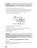
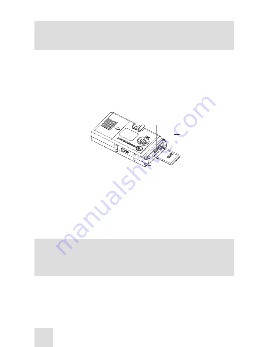
Insert the memory card as follows (refer to Figure 3-2):
1.  Open the cover of the memory card slot (1) on the side of the device.
2.  Insert a memory card (2). The gold-colored contacts should face down.
3.  Push the memory card into the slot until it locks into place.
4.  Close the cover of the memory card slot. 

FIGURE 3-2. SD CARD INSTALLATION

1

2

To remove the memory card, do the following:
1.  Turn the Recorder OFF. 
2.  Open the cover of the memory card slot on the side of the device.
3.  Push the memory card gently until it disengages.
4.  Remove the memory card.
5.  Close the cover.

CAUTION:

DO NOT remove the memory card while the device is transferring or 

accessing information. This could result in loss of data, or damage to 

the memory card or device.

3.1.3  MOUNTING THE RECORDER DT TO A SCOPE

A. MOUNT

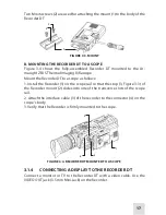
Figure 3-3 shows the rubber mount designed for installing the recorder on a 

digital scope Picatinny/Weaver rail.

Summary of Contents for Recorder DT

Page 1: ...Recorder DT Digital Video Recorder Operation and Maintenance Manual...

Page 2: ...afety Summary 4 How to Use This Manual 5 Chapter 1 INTRODUCTION 6 1 1 General Information 6 1 1 1 Type of Manual 6 1 1 2 Model Number and Equipment Name 6 1 1 3 Purpose of Equipment 6 1 1 4 Reporting...

Page 3: ...erating 19 3 3 2 Remote Operating the Recorder DT 20 3 3 3 Back up Power Mode 24 3 3 4 Recorder DT Shut Down 24 Chapter 4 PREVENTIVE MAINTENANCE AND TROUBLESHOOTING 25 4 1 Preventive Maintenance Check...

Page 4: ...ION Identifies risk of damage to the equipment NOTE Highlights essential procedures conditions statements and im portant instructional information CAUTION Do not dismantle the equipment Keep the equip...

Page 5: ...tenance before performing any kind of maintenance checks or procedures Follow all CAUTIONS and NOTES MANUAL OVERVIEW Throughout this Manual the Recorder DT Digital Video Recorder will be re ferred to...

Page 6: ...p re cording functionality as well as motion detection scheduled and manual recording options The SD card holds up to 32GB expandable and is enabled for direct TV monitor and PC playback using an SD c...

Page 7: ...handise sold as is by either Ar masight or the Armasight dealer or e merchandise that has been discon tinued by the manufacturer and either parts or replacement units are not available due to reasons...

Page 8: ...Customer Armasight s liability hereunder for damages regardless of the form or ac tion shall not exceed the fees or other charges paid to Armasight by the Customer or Customer s dealer Armasight shall...

Page 9: ...Contact information such as a valid telephone number and or e mail address and proof of purchase which will allow us to establish the valid start date of the Warranty Product merchandise returns that...

Page 10: ...IONS C Celsius Centigrade F Fahrenheit fps frame per second g gram hr hour m meter min minute mm millimeter NO Number PMCS Preventive Maintenance Checks and Services QTY Quantity SEQ sequence SR Servi...

Page 11: ...tweight but durable robust and designed to fit any Armasight Digital or Thermal scope Picatinny MIL STD 1913 or Weaver rail The rubber mount ensures quick easy and reliable mounting and disassem bly T...

Page 12: ...TION ITEM NO DESCRIPTION ITEM NO DESCRIPTION 1 Body 9 Cable Connector 2 Battery Compartment 10 SD Card not included 3 Battery Compartment Cover 11 SD Card Slot 4 CR123A Battery 12 Slot Cover not shown...

Page 13: ...torage SD SDHC Card Memory Support up to 32 GB Video Output Yes 3 5mm Mini Jack Remote Control Yes IR Remote Control Distance up to 5m Power Voltage 6 0 V Battery Type 2 x CR123A 3 0 V Operational Tim...

Page 14: ...The Recorder DT requires two CR123A batteries 2 3 Mount A rubber mount designed for installing the Recorder DT on a Picatinny or Weaver rail includes two mounting screws 1 4 Remote Control Used for re...

Page 15: ...itive sign on the battery com partment 3 Replace the battery compartment cover 1 Figure 3 1 BATTERY INSTALLATION 1 2 3 3 1 2 SD CARD Installation In order to store recorded video files you must insert...

Page 16: ...igure 3 2 SD CARD INSTALLATION 1 2 To remove the memory card do the following 1 Turn the Recorder OFF 2 Open the cover of the memory card slot on the side of the device 3 Push the memory card gently u...

Page 17: ...ll the Recorder 1 on the scope rail so that the stop 3 Figure 3 3 of the Recorder mount 2 slides into one of the transverse slots of the scope rail 2 Attach the interface cable 3 of the recorder to th...

Page 18: ...h Activates Recorder when turned ON Activates Back up Power Mode when in the BAT position Deactivates Recorder when turned OFF 2 REC Button Activates video recording when pressed once Stops video reco...

Page 19: ...ount the Recorder DT to a scope as per part 3 1 3 4 Attach the interface cable of the recorder to the connector on the scope s body 5 Turn the scope on 6 Turn the Recorder DT on An image will appear o...

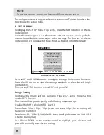
Page 20: ...lect Enter Esc To Last Page Menu To Main Menu Figure 3 6 SET UP MENU Use the UP and DOWN buttons to navigate through the items on the menu Press the OK button to view the settings available for the se...

Page 21: ...age Menu To Main Menu Figure 3 8 Recording Setting Menu This menu allows you to specify the following recording settings Scheduled time Start time Overwrite Overwrites the oldest recordings with new o...

Page 22: ...tion Detection The Recorder DT starts recording automatically when something enters the field of view of the connected digital scope Power Up Rec The Recorder DT starts recording automatically as soon...

Page 23: ...ngs C VIDEO RECORDING The camera icon in the upper right hand corner of the screen indicates that the device is in recording mode To begin recording press OK on the remote control The video icon will...

Page 24: ...ny connected digital scope To activate back up power mode turn the Recorder DT function switch to BAT 3 3 4 RECORDER DT SHUT DOWN Shut down the Recorder DT as follows 1 Switch off the equipment 2 Remo...

Page 25: ...r required for performing the checks and services LOCATION ITEM TO INSPECT CHECK SERVICE column Indicates the location and the item to be inspected checked or serviced Procedure column Details the che...

Page 26: ...n as required Cable is damaged Contacts are dam aged or corroded 6 Video Output Jack Inspect for moisture corroded or defective contacts Contacts are damaged or corroded 7 Mount Inspect for damage Che...

Page 27: ...4 2 OPERATOR TROUBLESHOOTING MALFUNCTION PROBABLE CAUSE TEST INSPECTION CORRECTIVE ACTION Recorder fails to activate no symbols on the screen Batteries are dead missing or improperly installed Replac...

Page 28: ...intenance consists of operational tests inspections for unit service ability cleaning and mounting procedures and corrective actions trou bleshooting and replacement of a limited number of parts Maint...

Page 29: ...followed to prevent any additional damage 1 Verify that the Recorder DT is free of all contaminants such as dirt or any other foreign material 2 Remove the batteries 3 Secure the covers 4 Place the Re...

Page 30: ...which can be found on our website at www armasight com Please complete the included form and im mediately mail it to our Service Center Armasight Inc 815 Dubuque Avenue South San Francisco CA 94080 US...

Page 31: ...rs used by the manufacturer to identify an item These numbers indicate the design and characteristics of the item by means of its engineering drawings specifications standards and inspection requireme...

Page 32: ...Armasight Inc 815 Dubuque Avenue South San Francisco CA 94080 USA Phone 888 959 2259 Fax 888 959 2260 Intl Phone Fax 650 492 7755 info armasight com www armasight com...

Reviews: