


PELLET STOVE KMP EKERUM / NEPTUNI
ARITERM SWEDEN AB
Installation Instructions -
2011.08.19
- 6
/24
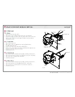
1.2 Komponenter
The top (1) lies loose on top of the stove steered by four bearings. The top is lifted to access
the cleaning hatch (2). The htch is opened by removing the four screws, one can then sweep
the flue (3) and the smoke tubes (4). The flue can easily be turned through 90˚, which makes
it possible to connect it to the chimney vertically or horizontally.
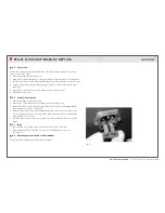
The front (5) can be opened. This is how one accesses the soot scrapers (6). These (four
per handle) can be slid forwards and backwards, and scrape off the soot between the
smoke tubes. The door (7) is opened with the handle supplied and can be swung up on its
two adjustable hinges. The burner housing (7) is located in the hearth and is accessible
when the door has been opened. It is installed with four screws on the rear of the stove body.
The burner (8) sits loose in the burner housing. The firing element (9) is located in the burner
housing behind the burner. It is the firing element that gives off the heat required to ignite
the pellets. The flame sensor (10) is beside the ignition unit and indicates if there is flame
in the burner or not. The ash box (11) is inset in the bottom of the hearth under the burner
housing. It can be removed when the door has been opened.
The combustion fan (12) is placed on the rear of the burner housing and provides the burner
with air for combustion. The control circuit board (14) is placed inside the stove and contains
a transformer for 12V-voltage to the electronics and control and supervision. The hot air fan
(15) is located inside the stove and sucks air from the rear of the stove, which is then heated
up in the smoke tubes and expelled through the holes in the front.
The pellet hopper (16) has space for 38 litres of pellets, and is filled through the top.
The pellet feeder (17) is below the pellet hopper and consists of a rotating cylinder with
a spiral spring that slowly turns at the bottom of the hopper and prevents blockages.
The patented design means that pellets cannot stick in the feeder. Safety thermostats (18)
are located on the:
1. fall pipe from the pellet feeder (85˚C),
2. the pellet feeder front wall (85˚C) and
3. the flue (204˚C)
The stove must not be modified and only spare parts recommended by the manufacturer
may be used.
Fig. 1
Electronic control
board (14)
Pellet feeder (17)
Pellet hopper (16)
Flue pipe (3)
Soot scrapers (6)
Door (5)
Ash tray (11)
Burner (8)
Covector fan (15)
Combustion fan (12)
Ignition element (9)
Flame sensor(10)
Burner housing (7)
Noice absorber
Cleaning lid (2)
Top (1)
Flue tubes (4)
Cut-out switches (18)


