Page 16
User Manual for CD72/95/15003
D
ISARMING A SPLIT SYSTEM AFTER AN ALARM
The bells and the flashing light are activated when an alarm is triggered in the system. If your system
has the option, a report of the event is automatically sent over the phone lines to a central station. If
you inadvertently activate an alarm, immediately telephone the central station to prevent an
unnecessary response.
When you enter the premises after an alarm, the bell may already be silent if it has been so
programmed, but the red LED will still be activated. This allows there to be several alarms. Remember
to record the fault or alarm in your logbook for future reference.
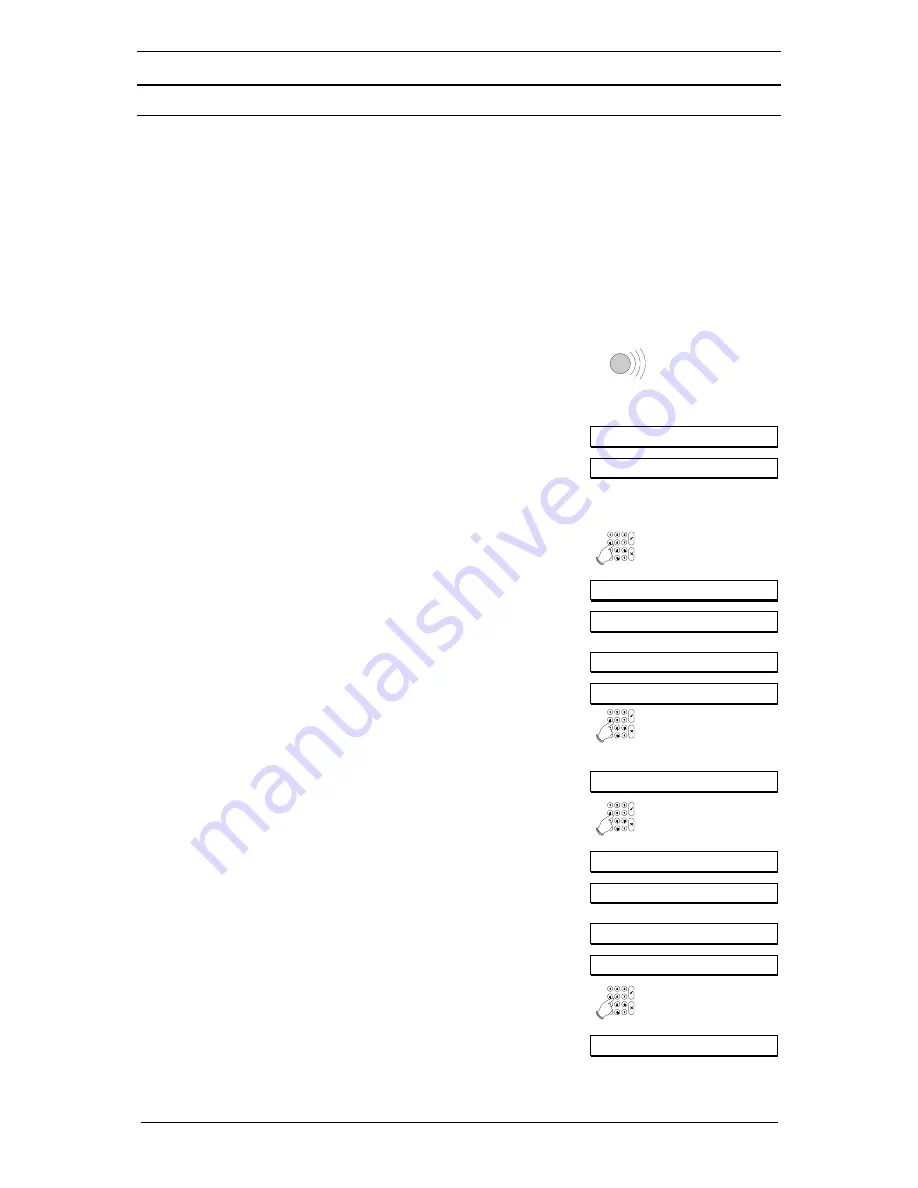
If your code allows you to access more than one security area, you can select one of them to disarm.
1.
Go to the keypad. The entry period starts as soon as you
open the entrance door, or when you enter the entry
zone. You can switch off the system without activating the
alarm as long as the beeping continues.
The
red
LED
ALARM
is lit on the keypad.
Beep Beep
The standby display is displayed. An example is shown.
TUE 23 APR 07.39
2.
Press the key
0
and then enter your code. A ‘*’ appears in
the display for every key you press. Use the
0
key to
cancel an incorrect entry and to restart a new entry of the
code.
Enter Code
0 + code
Enter Code ****
In this example, the area 1 alarm has been triggered and
area 2 is armed.
Area 1 Alarm
Area 2 Armed
Enter Area No.
3.
Enter the area number where the alarm occurred (in this
example it is 1). You have a few seconds to enter the
number.
1
Disarm?
4. Press
the
Accept
key to disarm the selected area (area 1
in this example).
!
!
!
!
A list of where the alarm was triggered is presented.
Events in Log...
In this example, the alarm was triggered in zone 4 ‘Back
Door’ on 23 April at 7.40am in area 1.
004 Alarm
004 Back Door
23 APR 05.20 A1
5. Press
the
Accept
key to confirm the alarm.
!
!
!
!
Area 1 Disarmed
Summary of Contents for ADVISOR CD72
Page 1: ...142360999 2 ADVISOR CD 7203 CD95 15003 User Manual Software from version V6 0 ...
Page 20: ...Page 20 User Manual for CD72 95 15003 Flowchart of the CD72 95 150 User Options ...
Page 21: ...User Manual for CD72 95 15003 Page 21 ...
Page 22: ...Page 22 User Manual for CD72 95 15003 ...


