background image

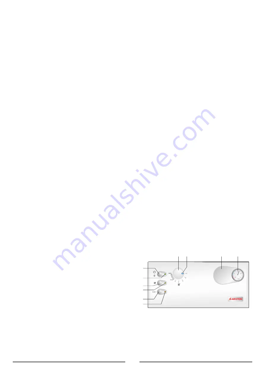
A

B
C
D
E
F

IL

GH

L

EGEND

:

A

- On/Off button

B

- On/Off L.E.D. green (frost protection active)

C

- Central Heating button

D

- Cental Heating active L.E.D. green 

E

- Ignition failure (lockout) and/or overheat reset button

F

- Ignition failure (lockout) and/or overheat L.E.D. red

G

- Central heating temperature adjustment

H

- Energy Saving System (ESS)

I

- Knock-out for time clock 

J

- Heating system pressure gauge

4.2

C

ONTROL

P

ANEL

F

IG

. 4.1

15

Close all air release valves on the central heating system.
Gradually open valve(s) at the filling point (filling-loop) connection to the central
heating system until water is heard to flow, do not open fully.
Open each air release tap starting with the lowest point and close it only when
clear water, free of air, is visible.

Purge the air from the pump by unscrewing anticlockwise and removing the
pump plug and also manually rotate the pump shaft in the direction
indicated by the pump label to ensure the pump is free.

Refit the pump plug.
Continue filling the system until at least 1.5 bar registers on the pressure gauge.
Inspect the system for water leaks and remedy any leaks discovered.

G

AS

S

UPPLY

:

Inspect the entire installation including the gas meter and test for soundness. The
gas installation should be in accordance with the relevant standards. In GB this is
BS6891 and in IE this is the current edition of I.S.813.

If the gas supply for the boiler serves other appliances ensure that an adequate
supply is available both to the boiler and the other appliances when they are in
use at the same time.
Pipe work must be of an adequate size. Pipes less than the 22mm should not be
used.
Open the gas cock (supplied with the connection kit) to the appliance and check
the gas connections on the appliance for leaks.
When the installation and filling are completed, flush the system while cold, refill,
turn on the Central Heating system (Section 4.4) and run it until the temperature
has reached the boiler operating temperature.
The system must then be immediately flushed through.
The flushing procedure must be in line with BS 7593:1992 code of practice for
treatment of water in domestic hot water central heating systems.

During this operation, we highly recommend the use of a central heating flushing
detergent (Fernox Superfloc or equivalent), whose function is to dissolve any foreign
matter that may be in the system.

Substances different from these could create serious problems to the pump or
other components.

The use of an inhibitor in the system such as Fernox MB-1 or equivalent is strongly
recommended to prevent corrosion (

sludge

) damaging the boiler and system.

Failure to carry out this procedure may invalidate the appliance warranty.

For IE it is necessary to complete a “Declaration of Conformity” to indicate
compliance to I.S.813. An example of this is given in the current edition of I.S.813.
In addition it is necessary to complete the “Benchmark” Log Book.


Summary of Contents for microSYSTEM 10 RFFI

Page 1: ...Installation Instructions Type C Boilers G C N 41 116 04 LEAVE THESE INSTRUCTIONS WITH THE END USER Country of destination GB IE...

Page 2: ...L VIEW 2 INSTALLATION 2 1 DELIVERY 2 2 REFERENCE STANDARDS 2 3 SITING THE APPLIANCE 2 4 OVERALL DIMENSIONS 2 5 CLEARANCES 2 6 MOUNTING THE APPLIANCE 2 7 ELECTRICAL CONNECTION 2 8 GAS CONNECTION 2 9 WA...

Page 3: ...immediately If you are going away for a long period of time remember to shut the mains gas tap or the gas cylinder valve Always disconnect the appliance either by unplugging it from the mains or turni...

Page 4: ...ing Regulations the bylaws of the local water authority in Scotland in accordance with the Building Standards Scotland Regulation and Health and Safety document No 635 Electricity at work regulations...

Page 5: ...uld be made to the current edition of I S 813 and the current ETCI rules If the boiler is to be sited into a timber framed building reference must be made to the current edition of the Institution of...

Page 6: ...een wire should be connected to the terminal marked with the symbol The blue wire should be connected to the terminal marked N The brown wire should be connected to the terminal marked L Note The diag...

Page 7: ...region contractor connects the gas meter to the service pipe The gas installation should be in accordance with the relevant standards In GB this is BS6891 and in IE this is the current edition of I S...

Page 8: ...ation R24 2 of the water regulations guide and for IE the current edition of I S 813 FILLING A temporary method for initially filling the system and replacing lost water during servicing and initial f...

Page 9: ...number A suitable terminal guard is available from TOWER FLUE COMPONENTS Morley Road Tonbridge Kent TN9 1RA The minimum acceptable spacing from the terminal to obstructions and ventilation openings ar...

Page 10: ...l N 4 For the time clock connect the clock switching wires to the positions 3 and 4 and connect the clock motor electrical supply to the terminals marked L and N Note A frost thermostat is built in to...

Page 11: ...FIG 2 13 11 FIG 2 12...

Page 12: ...elease valve 16 Expansion vessel 17 Air pressure switch A Central Heating Flow C Inlet Gas E Central Heating Return 2 13 GAS AND WATER CIRCUITS FIG 2 14 3 D H W STORAGE CYLINDER The microSYSTEM can be...

Page 13: ...using a 3 port valve installation in conjunction with an unvented cylinder it will be necessary to use a 2 port valve on the cylinder flow connection in addition to the 3 port valve to satisfy Buildin...

Page 14: ...ISTON part number 706329 can be obtained from an ARISTON supplier The kit consits of 1 Electronic module able to plug into the boiler s P C B 2 3 way priority valve with actuator for connection to the...

Page 15: ...f the gas supply for the boiler serves other appliances ensure that an adequate supply is available both to the boiler and the other appliances when they are in use at the same time Pipe work must be...

Page 16: ...s full If the water pressure in the system is below 1 5 bar bring it up to the appropriate level Ensure that the gas cock is closed Make sure that the electrical connection has been made properly and...

Page 17: ...urner If the burner does not light the first time repeat the procedure 5 Check the minimum and maximum pressure values for the gas going to the burner adjust it if needed using the values indicated in...

Page 18: ...2 8 3 80 58 29 20 0 77 2 9 0 91 22 9 80 58 37 25 0 77 2 9 0 90 29 5 TABLE 5 1 Lower Wobbe Index 15 C 1013mbar MJ m3 h Nominal Delivery Pressure mbar Minimum Delivery Pressure mbar 10 RFFI Main Burner...

Page 19: ...ck of the gas safety systems safety device for lack of gas or flame ionisation detection electrode safety device for gas cock 11 Check of the electrical connection make sure it complies with the instr...

Page 20: ...Pressure bar Nominal Pressure Natural Gas G20 mbar LPG G30 G31 mbar Electrical Supply V 5 V Hz Power Consumption W Protection Grade of Electrical System IP Internal Fuse Rating Weight Kg G C Number 6...

Reviews: