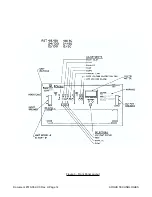


Front panel test points are connected to analog common and the negative output of the rectifier be-
fore the circuit breaker (-volt) through protecting resistors R15 and R16.
7.2.11
Rectifier Fail Detector
The rectifier fail circuit works by ramping up the output voltage of the rectifier if a low current condi-
tion occurs. If this does not reverse the low current condition, then a rectifier fail indication is given.
Rectifier fail is also indicated if the AC input voltage is insufficient, the output breaker is open or if
“Test” mode is selected.
Timer IC U17 provides an output of one second low and 10 seconds high at Pin 3, using compo-
nents R4, R6 and C6 to form the time constants. A set - reset latch consisting of NAND gates
U12/A and U12/B is set by pulse network C14, R35, R36 when pin 3 of U7 goes low. The latch’s
output activates the ramp circuitry. The latch is prevented from being set or is reset via a variety of
conditions as dictated by logic circuitry consisting of NOR gates U13/B, U13/C, U13/D and NAND
gate U11/D. Those conditions are: if a low current condition is not present as presented to the in-
puts of U13/D or, if the line voltage is low (Pin 2 of U13/C) or if the unit is in local sense (Pin 1 of
U13/C) or, if the output is at or above the O.V.P. trip point (Pin 8 or U13B). Thus the ramp is termi-
nated if output current is sensed. If the ramp latch is not reset after 1 second when the output of
the timer goes high, a second S-R latch, the rectifier fail latch, consisting of NAND gate U11/A and
U11/B is set as determined by a logic circuit consisting of U12/C and U12/D. This latch is reset by
the output of U11/D via an inverting function performed by NOR gates U13/A if output current is
sensed, the power is turned off or, if local sensing occurs. The output of the latch is presented to a
NAND gate which provides an OR function along with the output of U13/C so that a rectifier fail
condition is annunciated if the rectifier fail latch is set, the input AC voltage is low or, if the unit is in
local sensing (Local sensing occurs if the output breaker is open or if the unit is in “Test” mode). A
high condition of the output of U11/C, representing rectifier fail, turns off transistors Q1, and Q8 al-
lowing the front panel rectifier fail indicator DS7 to light and the rectifier fail relay K2 to de-energize.
The ramp is reset after 1 second even if the ramp latch is not reset by transistor Q9 and resistor
R129 driven from the output of U7.
Document #010-002-C0 Rev. H Page 28
ARGUS TECHNOLOGIES
Summary of Contents for RST 48/30
Page 1: ...RST 48 30 Switched Mode Rectifier Eliminator 010 006 B0 ...
Page 24: ...Document 010 002 C0 Rev H Page 14 ARGUS TECHNOLOGIES Figure 3 Front Panel Layout ...
Page 52: ......
Page 53: ......
Page 63: ......
Page 75: ......


