


7.1.8
Auxiliary Supply
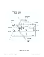
A +5 volt and -12 volt auxiliary supply is developed by three terminal regulators, U1 and U2 which
operate from “raw supply” voltages across C6 and C7 respectively. Capacitors C6 and C7 are
charged via full wave bridge modules D3 and D4 driven by the secondaries of 60 Hz 3 phase,
transformer T1 which operates from the output of CB1. Fuses F1 and F2 provides protection to T1.
Capacitors C8 and C9 provide a low impedance output for the auxiliary supply. Zener Diodes D7
and D55 protect the circuitry if either voltage regulator fails.
A circuit employing comparators U5/B and U5/C indicate to the front panel circuitry that the input
voltage is in the proper operating range. Diode D56 and D57 charge up C73 to a voltage propor-
tional to the line voltage. Transistor Q29 acts as a current source with R16 to ratio the input voltage
down (across R143) so it can be compared to the +5V reference of U6. Resistor R142 provides
hysteresis to prevent cyclic turn on/turn off with a higher impedance power source.
Transistor Q30 and resistors R17 and R28 prevent a power ON indication if the +5 volt auxiliary
supply is too low. Comparator U5/B prevents a power on indication if the +5 volt reference is low
which would happen if the -12 volt auxiliary supply is too low. A circuit consisting of comparators
U12A-U12C is used to detect imbalance of the 3 phase input voltage and to provide a phase fail
signal. Comparator U12D is used to provide a high level turn off of the vent.
7.2
Front Panel Circuitry
7.2.1
General
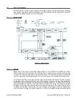
The RST 48/50 Front Panel Circuit Board provides the voltage, and current references to the power
board circuit. It incorporates all the front panel controls, selectors, indicators, remote control and
alarms of the rectifier. It provides the voltage and current controls, “Float” “Equalize” and “Test” se-
lector, the power on logic and start delay timer, the current limit and low current detectors, front
panel meter and test points and the rectifier fail detection circuitry. Please refer to schematic
#700-075-05 in order to follow the description of the circuitry.
7.2.2
Bias Supplies
The front panel circuitry runs from +5 volt and two -12 volt Bias supplies. All three supplies are
powered from the power board of the unit. In addition the supply marked -12 volts B is also pow-
ered from the output of the rectifier through diode D19 (and a regulator consisting of transistors
Q13, Q14, 13 Volt zener diode D18 and resistors R109, R108 and Diode D16). Diode D17 prevents
powering of the -12 Volt supply by the output of the rectifier. Transient absorbing diode D15 pro-
tects the front panel circuitry in the event of failure of the regulator. Capacitors C33, C34 and C35
bypass the Bias supplies.
7.2.3
References
Two voltage references are used, the main reference (U4) is used for developing the voltage and
current commands for the rectifier and the auxiliary reference U2 is used for the front panel voltme-
ter and monitoring circuits. U4 and U2, both small integrated circuits which incorporate a tempera-
ture compensated buried zener diode and buffer circuit, are biased by resistors R31 and R26 re-
spectively and bypassed by capacitors C11, and C8. Trimmer potentiometers R27 and R18 allow
adjustment of the references to nominally -6.150V while temperature sensitive resistor R119 gives
the main reference a nominal -100 ppm /C temperature coefficient to allow stable paralleling of
stacked units. Operational amplifiers U5/A and U3/A buffer the output of the trimmers to provide ref-
erences which are insensitive to loading.
ARGUS TECHNOLOGIES
Document #010-002-C0 Rev. H Page 25
Summary of Contents for RST 48/30
Page 1: ...RST 48 30 Switched Mode Rectifier Eliminator 010 006 B0 ...
Page 24: ...Document 010 002 C0 Rev H Page 14 ARGUS TECHNOLOGIES Figure 3 Front Panel Layout ...
Page 52: ......
Page 53: ......
Page 63: ......
Page 75: ......