


73
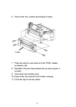
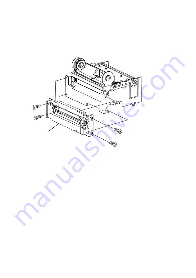
6. Secure the four screws attaching the cutter.
7. Plug the cutter's connector into the PCB's header
connector (J9).
8. Reattach the print head assembly by securing the 4
screws.
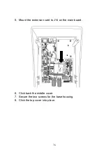
9. Click back the middle cover.
10. Secure the two screws for the base housing.
11. Click the top cover into place.
Cutter
Summary of Contents for OS-214 plus
Page 9: ...8 OS 214plus ...
Page 11: ...10 Media Hanger Ribbon Pick up Holder Release Levers Ribbon module not included with OS 2140D ...
Page 12: ...11 Power Switch Ribbon Supply Holder Thermal Print head Platen Roller ...
Page 16: ...15 Media Compartment Release Lever Print Head Module Release Lever Ribbon Supply Holder ...
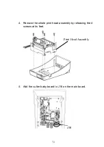
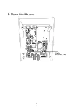
Page 76: ...75 4 Remove the middle cover Slot for Extension card ...