Argo AT0623 Installation, Operation & Maintenance Manual Download Page 17

17

Hydronic block requires only minimum of periodic 
maintenance. Preventive maintenance tasks 

described below are not difficult and when done 

annually, will aid unit to continue its trouble free 
operation.

Boiler is designed to provide years of trouble free perfor-

1. 

mance under normal operating conditions. Owner should 

conduct general external examination at beginning of 

each heating season and at mid-heating seating sea-

son to assure good working performance continues. A 

qualified service technician should examine at least once 

every year.

Do not store anything against boiler or allow dirt or 

2. 

debris to accumulate in area immediately surrounding 

boiler.

Elements will burn out if not filled with water when 

3. 

electrical power is turned on. Do not connect thermo-

stat wire until system has been filled with water. Drain 

water out of system only when absolutely necessary 

to make repairs or prevent freeze-up during extended 

cold weather shutdown.

Temperature and pressure gauge should be checked 

4. 

frequently. During normal operating conditions, pres-

sure should be stable throughout heating season. If 

pressure under normal operating conditions consis-

tently rises and falls over period of time, this can indi-

cate fill valve leak, system leak, or compression tank 

malfunction. Leaks anywhere must be repaired without 

delay. If leaks or significant pressure fluctuations are 

observed, call for service immediately.

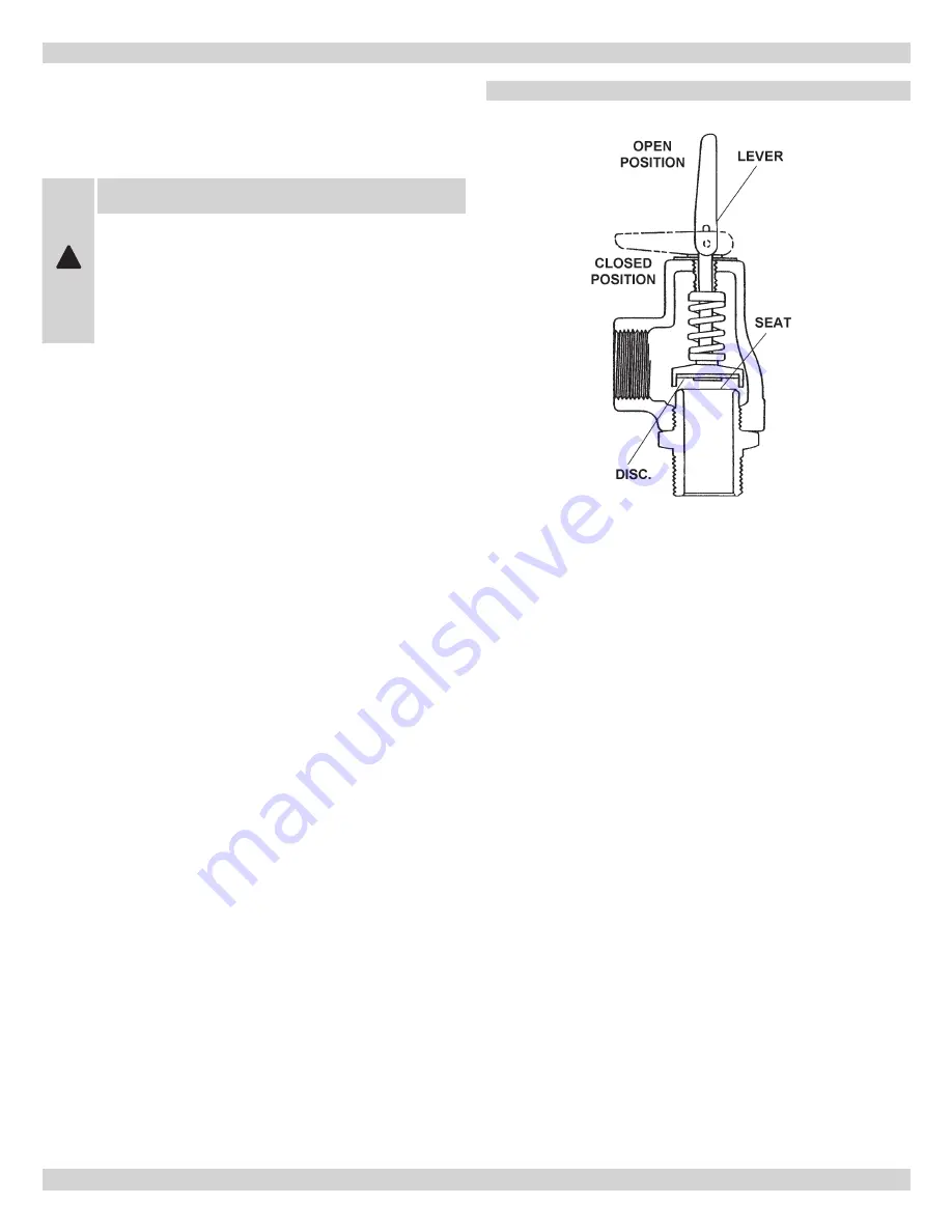
Check pressure relief discharge piping to assure 

5. 

discharged water will be properly routed to suitable 
container or drain. Manually operate pressure relief 
valve by pulling lever at end of valve until lever is in 
line with center-line of valve. (Figure 9) Close valve 
to avoid losing excessive amount of water. Repeat 
this procedure several times on quick cycling basis 
to release any sediment that could block relief valve 
pressure sensing mechanism. On heating system using 
manual water make-up or feed mechanism, do not to 
allow system pressure to drop to 0 PSI when cycling 
relief valve.  Allowing condition to occur could cause 
air to enter system requiring purging as described in 
“Startup and Seasonal Maintenance" on page 15.

figurE 9

If  relief  valve  fails  to  close  completely  after  cycling, 
remove it for cleaning or replacement. Turn off power 
to boiler and isolate hydronic block by shutting off inlet 
and outlet gate valves. Reduce water pressure to zero 
by opening relief valve.  Remove relief valve and inspect 
valve disc and seat. Cleaning parts with clean lint free 
cloth  may  be  all  that  is  necessary.  If  this  procedure 
fails replace valve with new one of equal pressure and 
discharge rating. After installing cleaned or new relief 
valve, open gate valves and follow procedure described 
in “Startup and Seasonal Maintenance" on page 15.

Inspect and check field entrance wire connections 

6. 

to unit for any signs of looseness or over heating. 

Verify wire lugs are tight and torqued to manufacture 
recommended settings - see Table B.

mAinTEnAncE

!


CAUTION

Turn off main power switch to block at main 

service entrance before any work requiring 

removal of cover is done for safety. All work 

shall be performed by qualified service 

personnel familiar with unit's control system 

operation.

Summary of Contents for AT0623

Page 1: ...n and specifications outlined in this manual in effect at the time of printing of this manual ECR International reserves the right to discontinue change specifications or system design at any time wit...

Page 2: ...NUAL NEAR BOILER RETAIN FOR FUTURE REFERENCE NOTICE Owner Installation and service of this boiler must be performed by qualified installer Installer Leave all instructions with the boiler for future r...

Page 3: ...nversion process requires no combustion boiler operates with highest possible efficiency Electric Hydronic Block is constructed with cast iron boiler that conforms to American Society of Mechanical En...

Page 4: ...t Boiler Recommended Wire AT0623 6 208 4 507 15 400 21 7 3 000 2 6 27 7 34 6 35 0 8 10 10 AT0824 8 208 6 009 20 500 28 9 4 000 2 6 34 9 43 6 45 0 6 8 8 AT1025 10 208 7 511 25 600 36 1 5 000 2 6 42 1 5...

Page 5: ...ting brackets for easy wall mounting Use of lag screws or anchor bolts through holes provided or on 3 4 plywood panel On uneven walls suggested mounting surface be provided such as two 2 x 4 s Surface...

Page 6: ...p supply may be located in this area below Circulator pump should be installed on supply side pumping away 6 Install gate valves at locations shown in Figures 2 3 so any boiler servicing requiring rem...

Page 7: ...7 primary secondary piping for Multiple zoning with ZONE VALVES primary secondary piping for Multiple zoning with circulators PRIMary secondary piping figure 2 figure 3...

Page 8: ...e ends before inserting into terminal block Tighten terminal screws Do not use pump rated greater than 5 amps Thermostat Connect thermostat or zone valve end switch to terminals TT and TT Figure 4 Do...

Page 9: ...re sizes specified conform to Canadian Electrical Code Canada or National Electric Code USA and include derating for ampacity and temperature Use copper wire only Check state and local requirements Re...

Page 10: ...or will continue to be energized for 3 minutes to purge boiler After 3 minutes control will de energize circulator Circ LED turns off If during start up or during operation safety end switch opens its...

Page 11: ...TACT SEC 120 VOLT WIRING POSE DES C BLES 120 VOLT 240 VOLT WIRING POSE DES C BLES 240 VOLT 120 VOLT FIELD WIRING POSE DES C BLES 120 VOLT SUR EN CHANTIER 240 VOLT FIELD WIRING POSE DES C BLES 240 VOLT...

Page 12: ...HERS SOURCE DU COURANT 120V 60HZ 1PH OU AUTRES OPTIONAL FLOW SWITCH BY OTHERS INTERRUPTEUR DE D BIT FACULTATIF OU AUTRES THERMOSTAT BY OTHERS THERMOSTAT OU AUTRES ELEMENT 1 L MENT No1 ELEMENT 1 RELAYS...

Page 13: ...T BLK BLANC NOIR WHT BLANC FUSE BLOCK BLOC DE FUSIBLE BLK NOIR L2 L1 POWER BLOCK BLOC DE PUISSANCE 240 VOLT FIELD WIRING POSE DES C BLES 240 VOLT EN CHANTIER EN CHANTIER 120 VOLT WIRING POSE DES C BLE...

Page 14: ...NOIR WHT BLANC RED ROUGE WIRE LEGEND L GENDE DES FILS DRY CONTACT WIRING POSE DES C BLES DE CONTACT SEC 120 VOLT WIRING POSE DES C BLES 120 VOLT 240 VOLT WIRING POSE DES C BLES 240 VOLT 120 VOLT FIELD...

Page 15: ...as the pressure remains less than 25 PSIG Hydronic block is now ready to be put into service Verify hydronic block circuit breaker or switch at service 1 entrance and depending on option hydronic blo...

Page 16: ...cluded with this manual Turn off hydronic unit circuit breaker at service en 1 trance and or disconnect switch Close gate valves near inlet and outlet of hydronic 2 block noisy boiler heating element...

Page 17: ...rly routed to suitable container or drain Manually operate pressure relief valve by pulling lever at end of valve until lever is in line with center line of valve Figure 9 Close valve to avoid losing...

Page 18: ...erature Pressure Gauge C57 Pressure Vessel Cast Iron 2 Element Z302A Control Panel Assembly 2 Element Complete 2 Element Electric Boiler w Power Block Item Part Number Description 1 S47 Safety Limit C...

Page 19: ...t Z304A Control Panel Assembly 4 Element Complete 4 Element Electric Boiler w Power Block Item Part Number Description 1 S47 Safety Limit Control High Limit Fixed Temp 2 G12 Gasket Heating Element 3 E...

Page 20: ...LATOR PUMP 120 VAC PRIMARY TT TT C1 C2 SINGLE ZONE WITH CIRCULATOR 2 BOILERS ONE SINGLE ZONE NOTE ABOVE NUMBERS REFER TO NUMBER DESIGNATIONS ON RELAY BASE 9 13 14 12 5 1 RELAY RELAY BASE 4 8 DIN RAIL...

Page 21: ...O ZONES WITH CIRCULATORS 2 BOILERS NOTE IF CONTROL ONLY CONTAINS ONE ISOLATED END SWITCH PLEASE CONTACT TECHNICAL SERVICE FOR PROPER INSTALLATION AT BOILER CIR CIRCULATOR PUMP 120 VAC PRIMARY TT TT C1...

Page 22: ...ONE VALVE ZONE VALVE ZONE VALVE THERMOSTATS THREE ZONES WITH CONTROL VALVES AT BOILER C1 C2 CIR CIRCULATOR PUMP 120 VAC TT TT PRIMARY X X ZONE 1 ZONE 2 TR TW SWITCH ISOLATED THERMOSTAT SPST 2 WIRE ARG...

Page 23: ...6 7 7 8 2 2 42 2 2 6 6 02 3352 4 0 2 452 5 02 3352 2 6 6 0 0 4 7 4 2 2 05 0 6 6 7 7 8 7 3500 9 2 6 6 6 6 80 3 4 2 3 0 2 4 2 54 4 2 6 4 7 7 7 7 6 6 6 6 6 6 6 6 4 4 7 6 6 6 6 4 5 2 2 0 0 2 5 4 2 05 0 6...

Page 24: ...LED should come on with the jumper installed OK OK Lights come on with jumper and elements then energize Replace circuit breaker or power block depending on type of boiler Check service at main load...

Page 25: ...ler and the output of all boiler circuit breakers 240vac not present 240vac present Replace circuit breakers Yes No Is there an increase in temperature 240vac not present Verify that 240vac is pres en...

Page 26: ...audible alarm flashing pulsing twice Stuck welded element relay contact Replace electric boiler control board RTD short Follow steps on page 10 to check RTD and replace if necessary RTD open Follow st...

Page 27: ...ry Yes Potentially bad low water cut off Check wiring to LWCO and consult LWCO manufacturer if necessary No Check pump and flow rate of system Pump may require replacement Does visual audible alarm sh...

Page 28: ...______________________________ ___________________________________________________________ Telephone Number ___________________________________________ After Hours Number _____________________________...

Reviews: