Subject to change_RPERX3-06_14095_1en_03/2022
Page 17
www.argo-hytos.com
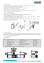
7.6.2 Replacing the sealing rings at the base of the valve body
In case of leaks in the dividing plane, the sealing rings must be replaced with new ones. The disassembly and reassembly procedure is similar.
› Ensure that no explosive atmosphere is present during the repair (see also 7.5)
› Switch off the pressure source (pump) of the hydraulic circuit (see also 7.5)
› Lighten the hydraulic circuit including the accumulators by connecting it to the tank (see also 7.5)
› Ensure that the hydraulic circuit is depressurised (see also 7.5)
› Switch off the electrical supply to the directional control valve solenoids (see also 7.5)
› Make sure that the surface of the valve and solenoid coils is cooled to a low enough temperature to prevent skin burns (see also 7.5)
› Clean the surface and surroundings of the directional control valve
› Loosen and unscrew the four fastening screws M5x45 DIN 912 using the inbus wrench a = 4. Carefully remove the valve from the
connection plate
› Allow the remaining working fluid from the valve to drain into the prepared smaller container
› Using a small screwdriver, remove the sealing rings from the recess in the body
› Work carefully to avoid damaging the sealing surfaces
› Clean the connection surfaces of the valve body and plate. Check them for damage
› Insert new sealing rings into the recesses in the valve body so that they do not fall out when the valve is reassembled
› Insert the four fastening screws into the holes in the valve body and fasten the valve to the plate using the inbus wrench a = 4. Tighten
the screws in a crosswise sequence to the specified torque of 8.9 + 1 Nm. Uneven tightening may cause deformation of the body and
unreliable valve function.
› If any of the fixing screws are damaged, replace them
WARNING
Valve mounting screws
The screws must be high tensile screws (SCREW M5x45 DIN 912 10.9), preferably from the valve manufacturer.
A screw of normal tensile can be broken due to the high pressure in the hydraulic circuit and can cause
massive leakage of the working fluid.
A defective valve that is not caused by a malfunctioning solenoid coil must be removed and replaced with a new one.
Repairs to a defective valve may only be carried out by the manufacturer.
When replacing the defective valve with a new one, proceed as follows:
› Ensure that no explosive atmosphere is present during the repair period (see also 7.5)
› Switch off the pressure source (pump) of the hydraulic circuit (see also 7.5).
› Relieve the hydraulic circuit including the accumulators by connecting it to the tank (see also 7.5)
› Ensure that the hydraulic circuit is pressure-free (see also 7.5)
› Switch off the electrical supply to the directional control valve solenoids (see also 7.5)
› Ensure that the surface of the valve and solenoid coils is cooled to a low enough temperature to prevent skin burns (see also 7.5)
› Disconnect the electrical supply cable to the coils (see 7.6.3)
› Switch off the electrical supply to the position sensor (if the valve is equipped with one) and disconnect the M12x1 connector
› Remove the coil surface ground wire by loosening the M5x10 ground screw
› Clean the surface and surroundings of the dirctional control valve
› Allow the remaining working fluid from the valve to drain into the prepared smaller container
Remove residual working fluid from the dismantled defective valve, seal the ports with a shipping plate and package it to prevent mechanical damage
and contamination of the area outside the package during transport. Send the packaged valve with a description of the manifestation of the defect
to the manufacturer.
A new valve is warranted by the manufacturer for 1 year. However, a claim may not be accepted by the manufacturer if the valve is mechanically
damaged, the seal material is damaged by aggressive liquid, or the valve has been shown to have been used improperly and not in accordance with
these instructions of use.
7.6.1 Replacing a defective valve
› Check that the coil cables in the grommet and the earth wires are properly secured to ensure that they are not loose when the valve is handled.
› After the repair, verify the new seals are tight and the valve is working properly.
Summary of Contents for RPERX3-06
Page 2: ...Subject to change_RPERX3 06_14095_1en_03 2022 Page 2 www argo hytos com ...
Page 3: ...Subject to change_RPERX3 06_14095_1en_03 2022 Page 3 www argo hytos com ...
Page 4: ...Subject to change_RPERX3 06_14095_1en_03 2022 Page 4 www argo hytos com ...
Page 21: ...Návod k použití_RPERX3 06_14095_1cz_03 2022 Strana 2 www argo hytos com ...
Page 22: ...Návod k použití_RPERX3 06_14095_1cz_03 2022 Strana 3 www argo hytos com ...
Page 23: ...Návod k použití_RPERX3 06_14095_1cz_03 2022 Strana 4 www argo hytos com ...


