background image

Subject to change_RPERX3-06_14095_1en_03/2022

Page 7

www.argo-hytos.com

The valves are available in three surface temperature classes:
T4

 with a maximum surface temperature of 135 °C

T5

 with a maximum surface temperature of 100 °C

T6

 with a maximum surface temperature of 85 °C

The use of the valve in the temperature class is subject to the maximum supply voltage of the coil not being exceeded, the working 
fluid temperature not being exceeded and the ambient temperature not being exceeded 

(see Table 4.4 Basic technical parameters)

2. Valve protection against initiation of explosion of explosive atmosphere 

2.1 Protection of electrical parts

The electrical part of the valve is an ATEX and IECEx certified solenoid coil. 
The basic type of protection is to pot the coil with potting compound „m“ (EN 60079-18, IEC 60079-18). For a DC-powered coil, protection is 
combined by potting the coil with „m“ using a terminal block with „e“ certification (EN 60079-7, IEC 60079-7).  
In addition, a fixed „t“ closure is used for dust (EN 60079-31, IEC 60079-31).

EPS14ATEX1744 X

IECEx EPS14.0064 X

AC

      l M2 Ex mb I Mb

Ex mb I Mb

      lI 2G Ex mb IIC T4, T5, T6 Gb

Ex mb IIC T4, T5, T6 Gb

      lI 2D Ex mb IIIC T135°C, T100°C, T85°C Db

Ex mb IIIC T135°C, T100°C, T85°C Db

DC

      l M2 Ex eb mb I Mb

Ex eb mb I Mb

      lI 2G Ex eb mb IIC T4, T5, T6 Gb

Ex eb mb IIC T4, T5, T6 Gb

      lI 2D Ex tb IIIC T135°C, T100°C, T85°C Db

Ex tb IIIC T135°C, T100°C, T85°C Db

2.2 Cable grommet

The cable grommet is a separately certified component with ATEX and IECEx certification:


I M2 Ex eb I Mb


II 2G Ex eb IIC Gb


II 2D Ex tb IIIC Db

2.3 Protection of non-electrical parts

2.4 Applicable legislation and standards

The valve complies with the relevant requirements of legislation and standards:
Směrnice 2014/34/EU 

(harmonizované NV ČR 116/2016) Zařízení pro prostředí s nebezpečím výbuchu (ATEX)

IECEx OD 009

 Operational Document

Standards used to assess the conformity of the electrical parts:
CENELEC EN IEC 60079-0


Explosive atmospheres – Part 0: Equipment – General requirements

EN 60079-7, IEC 60079-7

Explosive atmospheres – Part 7: Equipment protection by increased safety „e“

EN 60079-18, IEC 60079-18 

Explosive atmospheres – Part 18: Equipment protection by encapsulation „m“

FTZÚ 22 ATEX 0032X, IECEx FTZÚ 22.0004X

Non-electrical parts 
of valve

      I M2 Ex h I Mb
      II 2G Ex h IIC T4, T5, T6 Gb
      II 2D Ex h IIIC T135°C, T100°C, T85°C Db

The non-electrical part of the valve consists of the hydraulic part and the solenoid control system.
The safety of the non-electrical parts has been ensured and assessed according to ISO 80079-36, ISO 80079-37 and EN ISO/IEC 80079-38.

 › The moving parts, the spool/cone, armature and pin of the control system, perform a sliding motion in a space separated by a seal from  


  the surrounding environment and flooded with working fluid.

 › Not exceeding the maximum surface temperature of the given temperature class is conditioned by not exceeding the maximum temperature 

  of the working fluid (70 °C), the maximum ambient temperature (see table 4.4 Basic technical parameters) and the nominal voltage of the coil.

 › The valve body and spool body are of robust construction, sufficiently resistant to destruction by mechanical shock. 


  (Valve body impact resistance test performed according to EN IEC 60079-0 paragraph 26.4.2: two impacts with a weight with a hardened head of  

  diameter D25 mm, weighing m = 1 kg, falling from a height of 0.7 m, with a total potential energy of 7 J)

 › The hydraulic section has sufficient compressive strength, tested at 1.5 times the maximum operating pressure of the fluid.
 › The valve surface is grounded by a grounding screw and protected against static electricity discharge.
 › The construction materials used meet the requirements for limited content of certain elements to prevent the formation of electrical cells and  


  excessive corrosion.

 › The surface materials used do not create sparks during mechanical impacts.

 › The rotary pin of the manual emergency control lever is protected by a seal against the ingress of pollutants, especially hard particles, which could 

  create an initiation spark.

Summary of Contents for RPERX3-06

Page 1: ...R OVERRIDE DESIGNED FOR USE IN POTENTIALLY EXPLOSIVE ATMOSPHERES RPERX3 06 Operating instructions Important Read the instructions before using the product Save the instructions for future reference If the operating instructions are lost new ones can be found on the ARGO HYTOS website www argo hytos com The following is the authorised translation of original operating instruction RPERX3 06 no 14095...

Page 2: ...Subject to change_RPERX3 06_14095_1en_03 2022 Page 2 www argo hytos com ...

Page 3: ...Subject to change_RPERX3 06_14095_1en_03 2022 Page 3 www argo hytos com ...

Page 4: ...Subject to change_RPERX3 06_14095_1en_03 2022 Page 4 www argo hytos com ...

Page 5: ...nnecting the valve to the hydraulic circuit 14 7 3 Commissioning 15 7 4 Normal operation 15 7 5 Extraordinary and emergency situations 16 7 6 Repairs carried out by specialist 16 7 6 1 Replacing a defective valve 17 7 6 2 Replacing the sealing rings at the base of the valve body 17 7 6 3 Replacing the coil 18 7 7 Product maintenance 18 7 8 Spare parts supplied 18 7 9 Product disposal 19 8 Manufact...

Page 6: ...y manual lever operated emergency spool control that can be used up to 100 bar in the T port Valves with ATEX certification according to Directive 2014 34 EU and IECEx certification according to IECEx OD 009 and related harmonized standards may be used in explosive atmospheres consisting of mine gas gas or dust The valves are marked with the CE Ex mark of conformity and are accompanied by a Declar...

Page 7: ...ELEC EN IEC 60079 0 Explosive atmospheres Part 0 Equipment General requirements EN 60079 7 IEC 60079 7 Explosive atmospheres Part 7 Equipment protection by increased safety e EN 60079 18 IEC 60079 18 Explosive atmospheres Part 18 Equipment protection by encapsulation m FTZÚ 22 ATEX 0032X IECEx FTZÚ 22 0004X Non electrical parts of valve I M2 Ex h I Mb II 2G Ex h IIC T4 T5 T6 Gb II 2D Ex h IIIC T13...

Page 8: ...imit curves for each type of spool valve The hydraulic performance is provided as the product of the working pressure and the flow rate If the instant power exceeds the curve limit the valve may lose function The spool is subjected to excessive hydrodynamic forces the valve will not stop and as a result control of the appliance will be lost WARNING Valve installation The valve may only be mounted ...

Page 9: ...backdrop and does not reduce its performance CAUTION Use of the emergency manual control is forbidden when the valve solenoids are operational If the valve is operated by solenoids do not use the emergency manual control of the valve spool Valve damage and loss of function may result The emergency manual spool position control is used to reposition the spool in the event of loss of solenoid functi...

Page 10: ...r each surface temperature class T4 T5 T6 Temperature class Nominal coil input power C Ambient temperature range T4 135 C 10 W 30 70 T5 100 C 10 W 30 55 T6 85 C 10 W 30 45 IP68 test conditions product submerged 1m under water for 1 hour The valve is designed for common hydraulic working fluids mineral oils of performance classes HM and HV according to ISO 6734 4 non flammable and difficult to igni...

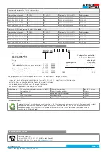
Page 11: ...plied with only the cable attached with optional lengths of 3 and 8 m as standard R30 Spool Symbols Type Symbol Interpositions Type Symbol Interpositions RPERX3 06 B 2 3 01200 02400 04800 11000 11050 23050 A19 B19 A4 A6 EAEU Eurasian Economic Union certificate according to TR TS 012 2011 valid for Russian Federation Belarus Armenia Kazakhstan and Kyrgyzstan For two position directional control val...

Page 12: ...tification label is affixed to the packaging The products should only be stored for the necessary time at a temperature of 0 to 30 C in a dry place with a relative humidity of up to 65 After extended periods of storage we recommend checking the product for corrosion damage replacing seal at the base of the body and flushing the product with clean oil before connecting it to the hydraulic circuit 7...

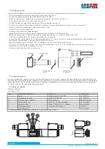
Page 13: ...supply and surge protection by bipolar diode Coils with AC power supply and rectifier UZ 36 V for UN 12 V DC a 24 V DC UZ 75 V for UN 48 V UZ 180 V for UN 110 V DC 1 2 1 2 After mounting the valve it is necessary to ground the coil surface by connecting the ground wire to the terminal on the surface of the terminal cover using an M5x10 screw Tighten the screw using an 8 mm screwdriver DANGER Corre...

Page 14: ... connection plate must have a sufficiently machined surface to ensure a seal in the dividing plane between the plate and the valve body 0 75 0 03 5 1 0 20 15 5 0 61 25 9 1 16 31 1 22 31 75 1 25 T P B A 4xM5 6Hx13 12 7 0 50 21 5 0 85 30 2 1 18 40 5 1 59 G ISO 4401 03 02 0 05 Ports P A B T max 7 5 mm 0 29 in Remove the shipping plate from the valve body Before assembly check the connection surfaces ...

Page 15: ... cooling surface of the hydraulic part of the valve Do not power separately disassembled coils Excessive winding heat insulation damage and short circuiting between coils may occur For the same reason the surface of the coils must not be covered exposed to direct heat sources or sunlight The valve must not be closed in a tight space without ensuring air circulation 7 3 Commissioning Before commiss...

Page 16: ...fore removing a valve Otherwise there is a risk of leakage of working fluid and contamination of persons WARNING Surface temperature Before starting disassembly make sure that the surface of the valve and solenoid coils has cooled to a low enough temperature to prevent skin burns ENVIRONMENTAL PROTECTION Spilled working fluid must be removed immediately e g with suitable absorbents contaminated pa...

Page 17: ...ressure in the hydraulic circuit and can cause massive leakage of the working fluid A defective valve that is not caused by a malfunctioning solenoid coil must be removed and replaced with a new one Repairs to a defective valve may only be carried out by the manufacturer When replacing the defective valve with a new one proceed as follows Ensure that no explosive atmosphere is present during the r...

Page 18: ...il Replace the sealing rings with new ones They are supplied in a set with the coil and a new fastening nut Put a new 22x1 5 sealing ring on the pipe a new coil with attached cable a new 21 89 x 2 62 sealing ring and screw on a new fastening nut Tighten the nut with a wrench to a torque of 5 1 Nm We recommend testing the valve after re mounting Valve body Control system Coil Fastening nut Sealing ...

Page 19: ...42139600 EX18 046 10W 110V AC 8M 10 110 EX22 46 11050 10W8M B 42139800 EX18 046 10W 230V AC 3M 10 230 EX22 46 23050 10W3M B 42140700 EX18 046 10W 230V AC 8M 10 230 EX22 46 23050 10W8M B 42140800 The storage conditions for seals are specified in ISO 2230 Rubber products Storage guidelines Seals to be stored in covered dry and tempered areas at temperatures of 15 to 25 C away from direct heat source...

Page 20: ...o 14095_1cz_03 2022 vydaný výrobcem Důležité Před použitím výrobku si pozorně přečtěte návod Návod k použití uchovejte pro budoucí potřebu Při ztrátě návodu k použití získáte nový na webových stánkách výrobce ARGO HYTOS www argo hytos com 4 3 a 4 2 ELEKTROMAGNETICKY OVLÁDANÝ HYDRAULICKÝ ROZVÁDĚČ S RUČNÍM PÁKOVÝM OVLADAČEM URČENÝ PRO PROVOZ V PROSTŘEDÍ S NEBEZPEČÍM VÝBUCHU RPERX3 06 NÁVOD K POUŽÍTÍ...

Page 21: ...Návod k použití_RPERX3 06_14095_1cz_03 2022 Strana 2 www argo hytos com ...

Page 22: ...Návod k použití_RPERX3 06_14095_1cz_03 2022 Strana 3 www argo hytos com ...

Page 23: ...Návod k použití_RPERX3 06_14095_1cz_03 2022 Strana 4 www argo hytos com ...

Page 24: ... provozu 15 7 4 Normální provoz 15 7 5 Mimořádné a nouzové situace 16 7 6 Opravy prováděné osobami znalými 16 7 6 1 Výměna vadného ventilu 17 7 6 2 Výměna těsnicích kroužků na základně tělesa ventilu 17 7 6 3 Výměna cívky 18 7 7 Údržba výrobku 18 7 8 Dodávané náhradní díly 18 7 9 Činnosti po skončení použitelnosti výrobku 19 8 Kontakt na výrobce 19 1 Na základě legislativních požadavků jsou všechn...

Page 25: ...Ventily s certifikací ATEX podle Směrnice 2014 34 EU a IECEx podle IECEx OD 009 a návazných harmonizovaných norem smí být použity ve výbušných atmosférách tvořených důlním plynem plynem nebo prachem Ventily jsou označeny značkou shody CE Ex a je k nim vystaveno Prohlášení o shodě Použití ve výbušných atmosférách Třída I doly kde je výbušná atmosféra důlního plynu tvořená převážně metanem Ventil má...

Page 26: ...EN ISO IEC 80079 38 Pohyblivé části šoupátko kuželka kotva a kolík ovládacího systému konají posuvný pohyb v prostoru odděleném těsněním od okolního prostředí a zaplaveném pracovní kapalinou Nepřekročení maximální povrchové teploty dané teplotní třídy je podmíněno nepřekročením maximální teploty pracovní kapaliny 70 C maximální teploty okolí viz tabulka 4 4 Základní technické parametry a nominální...

Page 27: ... teplotu Hrozí popálení pokožky VAROVÁNÍ Použité pracovní kapaliny Ventily smí být použity pouze pro obvyklé pracovní kapaliny zejména hydraulické oleje viz kapitola 4 Popis výrobku Jako pracovní kapalinu je zakázáno použít zejména vodu a vodní roztoky které způsobí korozi a ztrátu funkce ventilu kapaliny snadno zápalné nebo výbušné jejichž ohřevem při průchodu ventilem může dojít k požáru nebo ex...

Page 28: ...použití ručního nouzového ovládání je li ventil ovládán elektromagnety Je li rozváděč ovládán pomocí elektromagnetů nepoužívejte ruční nouzové ovládání šoupátka Může dojít k poškození ventilu a ztrátě jeho funkce Nouzové ruční ovládání polohy šoupátka slouží pro přestavení šoupátka v případě ztráty funkce elektromagnetu nebo při výpadku elektrického napájení cívek pro dosažení bezpečné polohy ovlá...

Page 29: ...ploty okolí pro jednotlivé třídy teploty povrchu T4 T5 T6 Teplotní třída Jmenovitý příkon cívky C Rozsah teploty okolí T4 135 C 10 W 30 70 T5 100 C 10 W 30 55 T6 85 C 10 W 30 45 IP68 podmínky testu výrobek ponořený 1 m pod vodou po dobu 1 hodiny Ventil je určen pro obvyklé hydraulické pracovní kapaliny minerální oleje výkonových tříd HM a HV podle ISO 6734 4 nehořlavé a obtížně zápalné hydraulické...

Page 30: ...y Označení Symbol Mezipolohy RPERX3 06 B 2 3 01200 02400 04800 11000 11050 23050 A19 B19 A4 A6 EAEU Eurasijský ekonomický svaz certifikát podle TR TS 012 2011 platný pro Ruskou federaci Bělorusko Arménii Kazachstán a Kyrgyzstán Pro dvouplolohové rozváděče s jednou cívkou páka je umístěna vždy mezi tělesem rozváděče a cívkou Upevňovací šrouby M5 x 45 ISO 4762 nebo svorníky se musí objednat samostat...

Page 31: ...základně jsou navíc chráněny plastovou PE přepravní deskou Na obalu je nalepen identifikační štítek Výrobky by měly být skladovány jen po nutnou dobu při teplotě 0 až 30 C na suchém místě s relativní vlhkostí vzduchu do 65 Po delší době skladování doporučujeme kontrolu nepoškození výrobku korozí výměnu těsnění na spodní základně tělesa a propláchnutí výrobku čistým olejem před zapojením do hydraul...

Page 32: ...cívky Hodnoty IG viz tabulka elektrických parametrů cívek Pro okruh pojistky musí být použity vodiče a prvky které jsou dimenzovány pro vyšší el proud než je maximální zkratový proud v obvodu zařízení zákazníka Pokud jsou prvky elektroinstalace včetně pojistky umístěny rovněž v prostředí s nebezpečím výbuchu musí také tyto prvky mít odpovídající stupeň ochrany Schéma elektrického zapojení cívek Cí...

Page 33: ...světlost DN 06 Připojovací deska musí mít dostatečně opracovanou plochu pro zajištění těsnosti v dělící rovině mezi deskou a tělesem ventilu 0 75 0 03 5 1 0 20 15 5 0 61 25 9 1 16 31 1 22 31 75 1 25 T P B A 4xM5 6Hx13 12 7 0 50 21 5 0 85 30 2 1 18 40 5 1 59 G ISO 4401 03 02 0 05 Kanály P A B T max 7 5 mm 0 29 in Sejměte z tělesa ventilu přepravní desku Před montáží zkontrolujte nepoškození a čisto...

Page 34: ...cívek počítá s chladící plochou hydraulické části ventilu Nezapínejte samostatně demontované cívky Může dojít k nadměrnému oteplení vinutí poškození izolace a zkratu mezi závity Ze stejného důvodu nesmí být povrch cívek zakryt vystaven přímým účinkům tepelných zdrojů nebo slunečního záření Ventil nesmí být uzavřen v těsném prostoru bez zajištění cirkulace vzduchu 7 3 Uvedení do provozu Před uveden...

Page 35: ...VAROVÁNÍ Teplota povrchu Před započetím demontáže se ujistěte že povrch ventilu a cívek elektromagnetů je ochlazen na dostatečně nízkou teplotu aby nedošlo k popálení pokožky Vadný ventil musí být vyměněn opraven OCHRANA ŽIVOTNÍHO PROSTŘEDÍ Vyteklá pracovní kapalina musí být neprodleně odstraněna např pomocí vhodných absorbentů kontaminované části obvodu očištěny kontaminované předměty v okolí oči...

Page 36: ...pevnosti může být přetržen díky vysokému tlaku v hydraulickém obvodu a může dojít k masivnímu úniku pracovní kapaliny Vadný ventil u kterého vada není způsobena nefunkční cívkou elektromagnetu musí být demontován a nahrazen novým Opravy vadného ventilu provádí pouze výrobce Při výměně ventilu a nahrazení vadného ventilu novým postupujte následovně Ujistěte se že po dobu opravy nebude přítomná výbu...

Page 37: ...ívku s připojeným kabelem nový těsnicí kroužek 21 89 x 2 62 a našroubujte novou upínací matici Matici dotáhněte pomocí klíče momentem 5 1 Nm Připojte k nové cívce vodič uzemnění Po ukončení výměny cívky zkontrolujte správnou funkci ventilu Těleso ventilu Ovládací systém Cívka Upevňovací matice Těsnicí kroužek 1 21 89x2 62 Těsnicí kroužek 2 22x1 5 7 7 Údržba výrobku Ventil během normálního provozu ...

Page 38: ... 110 EX22 46 11050 10W8M B 42139800 EX18 046 10W 230V AC 3M 10 230 EX22 46 23050 10W3M B 42140700 EX18 046 10W 230V AC 8M 10 230 EX22 46 23050 10W8M B 42140800 Podmínky skladování těsnění stanovuje norma ISO 2230 Pryžové výrobky Pokyny pro skladování Těsnění mají být skladována v krytých suchých a temperovaných prostorách při teplotách 15 až 25 C mimo přímé zdroje tepla chráněná před povětrnostním...

Reviews: