7
9)
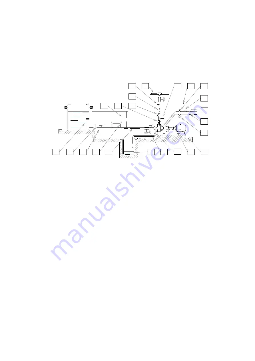
Fix the pump by the fixing holes provided: the supports must be level
10) YES: pipe discharge (completely sealed), discharge value shut during normal operations
11) YES: pipe fixing parts
12) YES: discharge collection well (does not leak)
13) Fluid speed suction: 2.5 m/s
14) NO: air pockets: the circuit must be short and straight
15) With positive head: tilt of piping towards pump
16) With negative suction lift: tilt of piping towards suction tank
17) YES: check vale (with negative suction lift)
18) YES: gate valve (may also be near pump in the case of long piping)
19) YES: line strainer (3-5 mm mesh)
20) YES: strainer (3-5 mm mesh)
21) Suction head, 3 m max.
22) Immersion depth: 0.3 m min.
YES: overcoming obstacles at lower depths.
(8xDN) mm
1
2
3
4
5
6
7
8
9
10
11
12
13
14
15
16
17
18
19
20
21
22
23
0,00
+
y
- anchor the pump to an adequate base plate having a mass at least 5 times that of the pump
- do not use anti-vibration mounts to fix the pump
- anti-vibration joints are recommended on the pipe connections
- manually verify that all rotating parts are free to turn without abnormal friction by turning the motor cooling fan
- make sure that the power supply is compatible with the data shown on the pump motor identification plate
- connect the motor to the power supply via a magnetic/thermal control switch
- ensure that star-delta starting is implemented for motors whose power is more than 15kW
- install emergency stop devices to switch off the pump in case of low liquid level (floating, magnetic, electronic, pressure-
sensitive)
- ambient temperature as a function of the physical-chemical characteristics of the liquid to be pumped and in any case not
greater or lower than the interval indicated in the GENERAL HINTS
- other environmental conditions in accordance with the IP protection of the motor
- install a drainage pit to collect any liquid overflow from the base drainage channel due to normal maintenance work
- leave enough free space around the pump for a person to move
- leave free space above the pump for lifting operations
- highlight the presence of aggressive liquids with coloured tags following the local safety regulations
- do not install the pump (made in thermoplastic material) in close proximity to heating apparatus
- do not install the pump in areas subject to solid or liquid matter falling
- do not install the pump in an explosive atmosphere unless the motor and its coupling have been adequately pre-arranged
- do not install the pump in close proximity to workplaces or crowded areas
-
install extra protection guards for the pump or persons as the need arises
-
install a spare equivalent pump in parallel
7.3
START-UP
-
verify that the instructions outlined in the INSTALLATION have been followed
-
verify that fixing elements (screws and bolts) are closed (see bolt torque on page)
-
verify the correct direction of rotation (clockwise from the motor side) supplying the motor with short impulses
-
ensure that the NPSH available is greater than that required by the pump (in particular for hot liquids, liquids with high vapour
pressure, very long suction pipes or negative suction lift)
-
close the discharge valve; completely cover the suction pipe and the pump.
-
close the outlet valve. Start up the motor two or three times with short supplies of current in order to expel the air from the
pump and the lubrication circuit between the guide shaft and bush.
-
start the pump with the suction valve completely open and the outlet valve semi-closed.
-
slowly adjust the flow by adjusting the outlet valve (never adjust the suction valve) and making sure that the motor absorption
is does not exceed the nominal power rating shown on the plate
Summary of Contents for ZMR 02.30
Page 2: ...2 1 DISASSEMBLING SEQUENCE ...
Page 16: ...16 ...
Page 17: ...17 ...
Page 18: ...18 ...
Page 19: ...19 ...


