


P12x/EN AP/A96
Application Guide
Page 10/80
MiCOM P120/P121/P122/P123
t
I
I>>
I>
t_I>
I> >> >>>Interlock NO
P0358ENa
I>
t
I>>
t
I>>>
t
I>
t
I>>
t
I>>>
t
t
I
I>>
I>
t_I>>
I> >> >>>Interlock YES
t_I>>>
I>>>
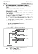
2.3
DMT thresholds
The three phase (earth) overcurrent thresholds can be selected with a time constant delay.
The time to operate is equal to the time delay set, plus the time for the output contact to
operate (typically about 20 to 30 ms ; 20ms for a current exceeding or equal to 2 times the
threshold) and the time required to detect the overcurrent state (maximum 20ms at 50Hz).
For DMT curves, a reset timer "t Reset" is associated with the first and second thresholds
(phase and earth elements).
2.4 IDMT
thresholds
2.4.1
Inverse time curves
The first and second phases (earth) overcurrent threshold can be selected with a dependent
time characteristic. The time delay is calculated with a mathematical formula.
There are eleven inverse time characteristics available.
The mathematical formula applicable to the first ten curves is:
t=T x (
K
(I/I
S
)
α
–1
+L )
Where:
t
= Tripping time
K
= Coefficient (see table)
I
= Value of measured current
I
S
= Value of the programmed threshold (Pick-up value)
α
= Coefficient (see table)
L
= ANSI/IEEE coefficient (zero for IEC curves)
T
= Time multiplier between 0.025 and 1.5
Summary of Contents for MiCom P120
Page 1: ...MiCOM P120 P121 P122 P123 Overcurrent Relays Version 11 Technical Guide P12X EN T A96...
Page 2: ......
Page 4: ...P12x EN T A96 Technical Guide Contents Page 2 2 MiCOM P120 P121 P122 P123 BLANK PAGE...
Page 13: ...Introduction P12x EN IT A96 MiCOM P120 P121 P122 P123 INTRODUCTION...
Page 14: ......
Page 16: ...P12x EN IT A96 Introduction Page 2 8 MiCOM P120 P121 P122 P123 BLANK PAGE...
Page 22: ...P12x EN IT A96 Introduction Page 8 8 MiCOM P120 P121 P122 P123 BLANK PAGE...
Page 24: ......
Page 35: ...User Guide P12x EN FT A96 MiCOM P120 P121 P122 P123 USER GUIDE...
Page 36: ......
Page 40: ...P12x EN FT A96 User Guide Page 4 72 MiCOM P120 P121 P122 P123 BLANK PAGE...
Page 108: ...P12x EN FT A96 User Guide Page 72 72 MiCOM P120 P121 P122 P123 BLANK PAGE...
Page 109: ...Menu Content Tables P12x EN HI A96 MiCOM P120 P121 P122 P123 MENU CONTENT TABLES...
Page 110: ......
Page 112: ...P12x EN HI A96 Menu Content Tables Page 2 68 MiCOM P120 P121 P122 P123 BLANK PAGE...
Page 180: ......
Page 221: ...Application Guide P12x EN AP A96 MiCOM P120 P121 P122 P123 APPLICATION GUIDE...
Page 222: ......
Page 226: ...P12x EN AP A96 Application Guide Page 4 80 MiCOM P120 P121 P122 P123 BLANK PAGE...
Page 302: ...P12x EN AP A96 Application Guide Page 80 80 MiCOM P120 P121 P122 P123 BLANK PAGE...
Page 304: ......
Page 306: ......
Page 368: ......
Page 370: ...P12x EN CT A96 Communications COURIER DATABASE Page 2 248 MiCOM P120 P121 P122 P123 BLANK PAGE...
Page 514: ...P12x EN CT A96 Communications COURIER DATABASE Page 146 248 MiCOM P120 P121 P122 P123...
Page 516: ......
Page 518: ...P12x EN CT A96 Communications IIEC 60870 5 103 Page 2 248 MiCOM P120 P121 P122 P123 BLANK PAGE...
Page 536: ...P12x EN CT A96 Communications IEC 60870 5 103 Page 20 248 MiCOM P120 P121 P122 P123...
Page 538: ......
Page 540: ...P12x EN CT A96 Communications DNP 3 0 Database Page 2 248 MiCOM P120 P121 P122 P123 BLANK PAGE...
Page 554: ......
Page 573: ...Connection Diagrams P12x EN CO A96 MiCOM P120 P121 P122 P123 CONNECTION DIAGRAMS...
Page 574: ......
Page 580: ......
Page 582: ...P12x EN RS A96 Commissioning Test Record Sheets Page 2 60 MiCOM P120 P121 P122 P123 BLANK PAGE...
Page 642: ......
Page 667: ......