


Arecont Vision MegaView
®
2 Installation Manual
Page | 17 [email protected]
compression and result in higher
quality images with trade off for
larger file sizes. Lower levels
increase image compression
reducing file sizes with the trade off
for lower quality image detail. Valid
numeric values that can be entered
here are 16 to 36. The configured
value will be constant default unless
rate limit or constant bit rate control
are selected
ii.
Enable Rate Limit
this radio button
enables operation of the bit rate limit
feature for H.264
iii.
Rate limit
this numeric field allows
setting the maximum bit rate limit for
Variable bit rate control. Valid values
that can be entered are 0 to 65535
kbps. When active the bit rate will
vary depending on camera
resolution, illumination, and scene
content until it exceeds the
configured limit. When this limit is
exceeded image compression will be
increased in attempt to keep the bit
rate within the configured limit
Constant Bitrate Control
when active this
radio button enables the constant bit rate
control feature. Unlike variable bit rate
control option constant bit rate control will
set a hard limit for the bit rate. Image
compression will be set to whatever value
achieves the configured bit rate. This
method of bit rate control can achieve a
more consistent overall bit rate. Image
quality will be dependent on camera
resolution, illumination, and scene content
based on the constant control limit
configured
i.
Bitrate
this numeric field allows
setting the bit rate value for constant
bit rate control. Valid values that can
be entered are 0 to 65535 kbps
Frames per second
this slider bar control
allows setting a frame rate output limit for
the H.264 video stream. Default value is
“Max” minimum fps is 1. Reducing the frame
rate output is another way to control the
bandwidth used for the H.264 video
streaming from the camera trade off is the
obvious reduction of frame rate output at the
camera
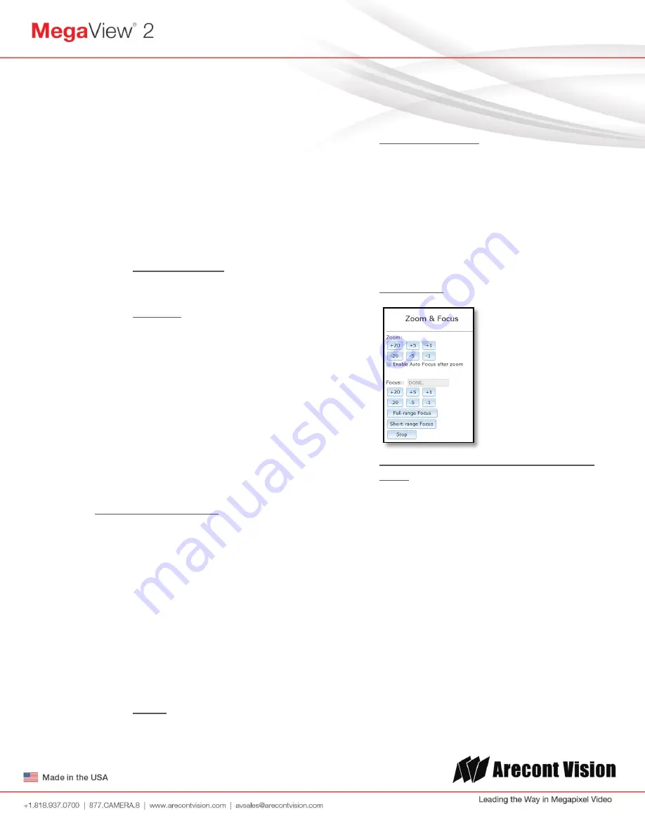
5. Focus Menu
Adjusting the Remote Focus and Remote
Zoom
i.
To manually adjust zoom, click the
“+20”, “+5”, “+1”, “-20”, “-5”, “-1”
buttons to zoom in and out, adjusting
the field of view
NO
TE 1: “+20” zooms in 20x further than
“+1”
NOTE 2: If the “Enable Auto Focus after
zoom” option is checked, the focus will
automatically be adjusted when zoom is
changed.
ii.
Set up a focus area (if necessary) by
drawing a rectangle with the mouse
(by left-clicking and dragging the
mouse to a desired zoom size)