


MegaDome® 2 I/O Cable Connection
Inside the box:
A. I/O Cable
Image 40
Not included but needed:
B. Flat head screwdriver
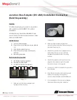
1. To use the I/O ports of the
MegaDome®, run the I/O cable through
the hole in the bottom of the camera and
plug it into the connector as shown in
Image 41.
NOTE: The connection is a little stiff so
be sure to apply enough pressure to
connect it; using a flat head screw driver
to push it in is recommended.
Electrical Characteristics:
Min Max
Input voltage (V)
ON
2.9
6.3
(measured b and
–
terminals)
OFF
0
1.3
Output current (mA)
ON
-
50
(measured b and
– terminals)
Applied Voltage Rage: 0 - 80V
OFF
-
0.1
Table 1
Image 41
NOTE: Both the input and the output are
electrically isolated from the rest of the
camera’s electrical circuitry via general-purpose
photo couplers. The input is additionally
protected with a serial 250 Ohm resistor and a
debouncing circuit. Duration of any input signal
should be at least 5ms to comply with the
requirements of the debouncing circuit.
Orange
OUT +
Yellow
OUT
–
White
IN +
Black
IN -
Table 2
A
I/O
Connector


