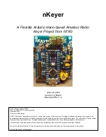


nKeyer
Page 5 of 15
Version 1g
By N7XG / KI6TMF
2.
Assembly Instructions
This section covers the construction of the nKeyer. It approaches assembly as a learning
exercise for new builders, so that they can develop proficiency and self-confidence. The build
is quite simple and if you follow the steps carefully, you should have a working board when you
are done. Additional information and guides on techniques and tools can be found in the
“Tools and Parts ID Guide” at:
www.renard-plus.com/files/Tools_and_Parts_ID_Guide.pdf
2.1
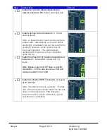
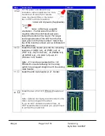
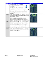
nKeyer board BOM/Parts List
Picture
Designators
Description
Qty
Note
R1, R5
470 ohm resistor ¼ watt
2
R2, R4, R6, R7, R9-R14
1.0k ohm resistor ¼ watt
10
R3
10k ohm resistor ¼ watt
1
R8
100 ohm resistor ¼ watt
1
C1, C2, C4
.01uf (10nf) 50v
monolithic ceramic cap
3
C3 Optional for DC
blocking on the audio out.
Jumper wire (or 1uf -
220uf electrolytic or
tantalum cap)
1
Typically not used -
jumper across
C5
220uf 16v electrolytic
1
D1
1N4148 diode
1
U1 (opt but
recommended)
1x15 pin 2.54 pin
spacing female header
2
Allows the Nano to be
removed replaced
U1
Arduino Nano 3.0
16MHz, 5V,
ATMEGA328P
1
U2 (opt for >5v input)
Mini “360” Buck
regulator (adjust to 5v
output)
1
If your input is 5V, this
can be left out by placing
a jumper across JP1
“Buck bypass”
Q1, Q2
2N2222a or 2N3904
NPN Transistor
1
J3-PWR LED, J5-TX LED LED Standard 5mm (any
color)
2
Place header pins if LED
will be mounted on the
enclosure.
J1-1x4, J2-1x2, J4-1x3,
J6-1x2, J8-1x3, J9-1x2,
J10-1x5, J11-1x5
Single row headers
–
various
30
pins
Cut to appropriate # of
pins for the location
J7 Buttons 2x8
2x8 dual row header
1


