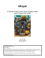


nKeyer
Page 15 of 15
Version 1g
By N7XG / KI6TMF
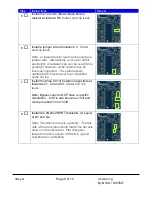
5. LCD (J10: LCD
Pinout = “GND, 5V, SDA, SCL, 3.3v” ) –
The board will drive a Serial LCD character display.
Most display run on 5v and will hook straight to the first 4
pins
– HOWEVER- if the display you have needs 3.3v,
that is also provided on the connector. The code is
designed specifically for a “Serial 1602 LCD” that can be
found on ebay for around $2.
RECOMMENDED
6. Keyboard (J1: KBD
Pinout = “GND, 5V, KBD-CLK, KDB-
DATA”). In theory, the code supports attaching a P/S2 or USB keyboard. This is an
untested option as of publication of this document.
OPTIONAL
7. LED Power (J3: PWR LED Pinout =
“LED+, LED-“)– This is a spot to directly hook an
LED to indicate the power is on. There is a limiting resistor that keeps the
voltage/current within range of modern 2.7 - 3V LEDs.
RECOMMENDED
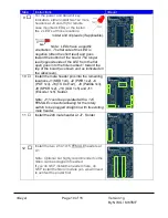
8. Transmit LED (J5: TX LED Pinout =
“LED+, LED-“)– This attaches to an LED to
indicate when the Transmit Out (TX Out) is active.
RECOMMENDED
9. Transmit Out (J6: TX OUT Pinout =
“TX+, TX-“) – This connection is used to key up
your transmitter to send out code via the speaker connection.
RECOMMENDED
10. Paddle Input
– (J8: PADDLE Pinout = “L, GND, R”) This connector is used to connect
to your Paddles to have the nKeyer send out morse tones. One pin is the “Dit”, one is
the “Dah” and the middle pin is ground to the paddle.
NEEDED
11. Speaker Out (J9: SPKR Pinout =
“Spkr+, Spkr-“) – This connection is to either hook
directly to a speaker, or to the microphone input on your transmitter to allow the nKeyer
to send out morse.
NEEDED
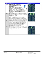
12. Buck Bypass (JP1: No Buck Jumper)
– If you will be using a clean 5V regulated input on
J2 PWR IN (or will power off the USB connection on the Nano), you do not need to
install the Mini-360 Buck Converter, but instead can jumper JP1. This will connect J2
straight to the 5V power bus on the board. If you attach any power higher than 5V in
this configuration, it WILL blow up the board. Either a MINI-360 or a jumper is
NEEDED


