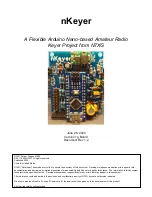
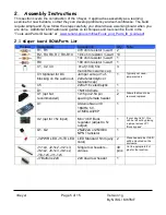


nKeyer
Page 10 of 15
Version 1g
By N7XG / KI6TMF
Step
Instructions
nKeyer
9
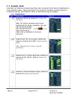
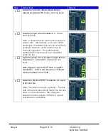
For the power and transmit key
indicators, either install two 1x2 male
headers at J3 and J5 (for remote
case mounted LEDs) or the install
the 2 LED’s at those locations.
So
lder and clip leads (if applicable).
Note: LEDs have a specific
orientation. The flat side of the LED is
negative (often the short lead) and goes
toward the bottom of the board. The longer
lead (opposite side of the LED from the flat
spot) goes into the hole toward the
top of the board (as shown and as indicated on
the silkscreen).
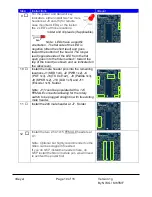
10
Install the male header pins into the remaining
locations J1 (KBD 1x4), J2 (PWR 1x2), J4
(POT 1x3), J6 (TX Out 1x2), J8 (Paddle 1x3),
J9 (SPKR 1x2), J10 (LCD 1x5) and J11
(Encoder 1x5). Solder.
Note: J11 could be populated with a 1x5
FEMALE connector allowing for the rotary
switch to be plugged straight in with its existing
male header.
11
Install the 2x8 male header at J7. Solder
12
Install the two 2.54 1x15 FEMALE headers at
U1.
Note: Optional but highly recommended so the
Nano can be swapped if needed.
If you do NOT install the headers here, do
NOT install the Nano module yet- we will need
to set/test the power first.


