ArcVision Technology ARC 19601 User Manual Download Page 41


4.Live view via IP network 

Click Remote Viewer icon to view live pictures via IP network. You will see then 
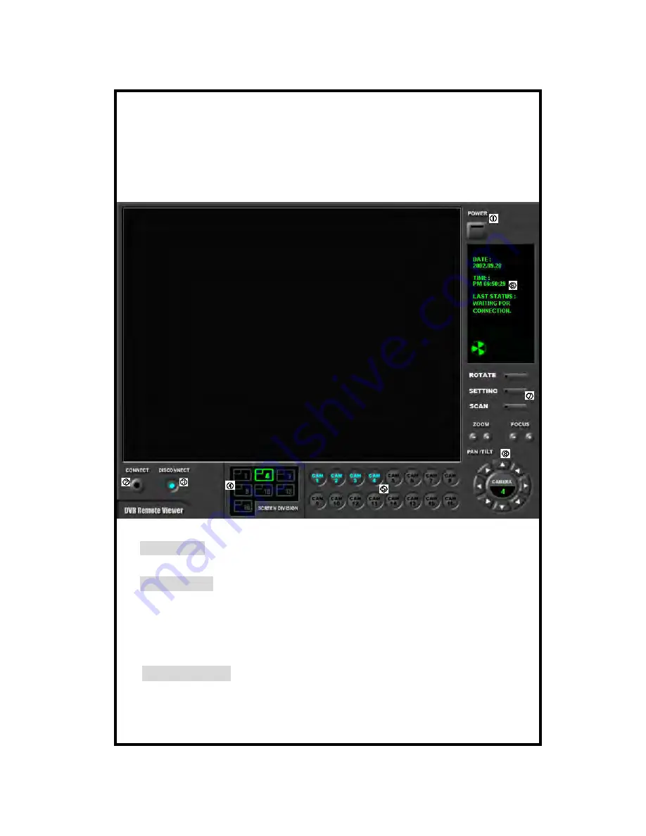
following window. 

Function of each button in live-view window : 


:

 Power switch. Press power switch to quit. Before press power switch button, press 

disconnect button first. 

  :

 Connect button. Press connect button to connect to DVR unit via IP network to see 

live pictures of DVR unit. You will see the same live pictures, which are displayed 

on monitor 

of DVR unit with a certain time delay depending on transfer rate of IP network. 


:

 Disconnect button. Press disconnect button to cut connection to DVR unit via IP

network  for seeing live pictures of DVR unit. 


- 41 - 

Summary of Contents for ARC 19601

Page 1: ...1CH Digital Video Recorder Thank you for purchasing our product Please read this User s Manual before using the product 1 Channel Digital Video Recorder V1 1 1...

Page 2: ...lamation point within an equilateral triangle is intended to alert the user to presence of important operating and maintenance Servicing instructions in the literature accompanying the appliance WARNI...

Page 3: ...ONNECTION 10 6 POWER CONNECTION 10 OPERATION 11 1 LOG IN 11 2 RECORDING 12 3 PLAY 15 4 SETUP 17 1 Start of SETUP 17 2 DISPLAY SETUP 19 3 CAMERA SETUP 19 4 TIME DATE SETUP 21 5 ALARM MOTION SETUP 22 6...

Page 4: ...MANUAL FOR REMOTE VIEWER SOFTWARE 37 1GENERAL DESCRIPTION 37 2 TCP IP SETUP IN DVR UNIT 37 3 STATIC IP AND DYNAMIC IP 38 4 LIVE VIEW VIA IP NETWORK 41 5 SEARCH RECORDED PICTURES VIA IP NETWORK 45 4...

Page 5: ...to install the DVR unit is stable and meets our electricity requirements Unstable electricity will cause malfunction of the unit or give critical damage to the unit 2 Several chips on the main board...

Page 6: ...PEED In full screen this button shows pictures in rotation MARK mark when it is in playback mode FRZ On off switch to freeze pictures in live mode PLAY Play Back MENU used to change menu in system set...

Page 7: ...2 Rear Panel HDD BOX TRIGGER RJ45 LOOP BACK VCR RS232 RS485 IO ALARM Connection DC Power VIDEO OUT 7...

Page 8: ...reen this button shows pictures in rotation MARK mark when it is in playback mode FRZ On off switch to freeze pictures in live mode PLAY Play Back MENU used to change menu in system setup ENTER Used a...

Page 9: ...INSTALLATION 1 Camera connection Connect camera the camera input on the rear panel of the system 2 Monitor connection Connect the monitor to the monitor out on the rear panel of the system 9...

Page 10: ...R TRIGIN GND 4 Network connection Connects to HDD BOX Multiplexer or network 5 HDD connection Be sure to set jumper setting for each HDD as per HDD manufacturer s spjecification Main board HDD Default...

Page 11: ...n to enter password that has 1 to 8 digits with numbers from 1 to 4 4 Use MENU button to change 5 After entering the password press ENTER button to go back to the system menu If password entered match...

Page 12: ...REC CAM1 Indicates current time Recording basic screen TIMER recording Indicate recording speed 60FPS Records 60 fields sec MOTION REC Records when motion is detected 001MUX Records in connection with...

Page 13: ...sor recording When there is sensor input recording starts It records for preset period of time RECORD SETUP HDD CLEAR HDD FULL RECORD MODE RECORD SPEED MUX CH NUMS SELECT PRESS NO OVERWRITE MOT ARM 60...

Page 14: ...more details refer to SCHEDULE REC SETUP in MISCELLANEOUS SETUP in page 29 5 Recording motion detection Refer to ALARM MOTION SETUP in page 25 It must be set at MOTION or MOT ALM to record whenever m...

Page 15: ...GOTO Set time from which playback starts Display of Playback 2 GOTO time settings Select G GOTO submenu and move cursor using key to set Using key set year month date time at which you want to to sta...

Page 16: ...X PLAY SPEED 4X PLAY SPEED 8X PLAY SPEED 16X PLAY SPEED 32X PLAY SPEED 60X PLAY SPEED Press 1X PLAY SPEED 1 2 PLAYSPEED 1 4 PLAYSPEED 1 8 PLAYSPEED 1 16 PLAYSPEED 1 32 PLAYSPEED 1 60 PLAYSPEED 2002 AP...

Page 17: ...o select SEPUP item and press MENU button to go back to previous menu If you choose FACTORY DEFAULT all settings shall be changed to settings done by manufacturer and we recommend you to set at FACTOR...

Page 18: ...ULT Display of SYSTEM SETUP SETUP items remain unchanged even though you choose FACTORY DEFAULT 1 Time and date of TIME DATE SETUP 2 All recorded data on HDD 3 Marked data 4 ADMIN password 5 ALARM LIS...

Page 19: ...screen B If CAMERA TITLE is on camera title is displayed on live screen C If TIME and DATE is on time and date of recorded pictures is displayed in playback D If PB CAMERA TITLE is on camera title is...

Page 20: ...0 1 2 3 4 5 6 7 8 9 A B C D E F G H I J K L M N O P Q R S T U V W X Y Z a b c d e f g h I j k l m n o p q r s t u v w x y z CH1 CAM 1 Display of CAMERA TITLE SETUP COLOR BAR TEST Displays COLOR BAR CH...

Page 21: ...y hour minute second and change value using button SET TIME DATE TYPE Sets notation of TIME DATE TIME DATE TYPE SETUP HOUR DISPLAY DATE DISPLAY MONTH DISPLAY SELECT PRESS AM PM ASIAN ENGLISH Display o...

Page 22: ...ATION Duration of recording when an ALARM is activated set time 10 20 30 40 50 sec 1 MIN 3 MIN 5 MIN SELECT LIST TYPE A indicates Alarm L indicates Loss and M indicates Motion You can select group of...

Page 23: ...ce of ALARM LOSS and MOTION 1 DATE TIME Order in data and time 2 ALM Order in type ALARM LOSS MOTION 2 DELETE When DELETE is selected you can enter into any one of MARK PAGE ALL Move to any one of 3 u...

Page 24: ...choose from 1 to 20 If DETECT DELL is set at 5 motion detection is activated only in case 5 DETECT CELLs are simultanuously activated MOTION REC DURATION Sets recording time when a motion is detected...

Page 25: ...l cells in a vertical line SELECT HOR LINE Selects all cells in a horizontal line SELECT AREA Select areas SELECT BLOCK Select BLOCK When ENTER button is pressed ON is displayed in the first line MODE...

Page 26: ...records at its maximum recording rate 60 FPS for ALARM DURATION 3 MOTION The system records just when motion is detected for MOTION DURATION 4 MOTION ALARM The system just records when motion is dete...

Page 27: ...eway and Subnet mask and install Remote Viewer program in client PC from which you are going to access to DVMR unit For detail procedure for installing Remote Viewer program and settings refer to Remo...

Page 28: ...enter REQUEST IP You have to memorize this IP information and input this information into SETTING of Remote viewer program installed on your PC client PC If it fails to connect automatically or you se...

Page 29: ...ent number first and enter new number Numbers must be equal or less than 8 digits and each digits must be from 1 to 4 Default setting ADMI PASSWORD 1 USER PASSWORD 2 Change PASSWORD to your own one as...

Page 30: ...ecord and OFF means not to record After completing to set schedule press MENU button to leave In RESET mode you can delete recording schedule Using button move to the date to delete and press ENTER bu...

Page 31: ...SETUP For details refer to Manual for incorporating PTZ protocols PANTILT COMMAND SETUP SELECT PRESS ENTER DRX 502A DEFAULT USER DEFINE SETUP Display of PANTILT COMMAND 1 DRX 502A DEFAULT 2 AECD 2000...

Page 32: ...st MARK button and 2nd MARK button are all marked and stored separately on HDD 4 If you mark many images instead of choosing image by image cancel PAUSE by pressing PAUSE button in step 1 Images are r...

Page 33: ...needs to increase storage capacity connect HDD Bay to DVMR unit Models of Tera Tray TeraTray 04 Includes up to 4 HDDs TeraTray 10 Includes up to 10 HDDs TeraTray 20 Includes up to 20 HDDs 1 Configura...

Page 34: ...nnel stand alone DVMR TCP IP 1 59SEC CONTINUOUS TIMING ESTABLISHMENT POSSIBILITY PREVIOUS VCR TIME LAPS VCR USAGE VCR OUTPUT UTILIZATION REMOTE BACK UP USING TCP IP RS232C RS485 MAX 4 ALARM INPUT PAN...

Page 35: ...rs who want to control the DVMR unit via RS 232C port If you connect to RS 232C you can operate DVMR unit using key board of PC in addition to operation using operation buttons on the front of DVMR un...

Page 36: ...Remote Viewer Software Thank you for purchasing our product Please read this User s Manual before using the product 4 Channel Digital Video Recorder V1 1 36...

Page 37: ...and alone DVR does not include web server for access to DVR unit via Internet line and you must install Remote Viewer software included in the package on client PC before you try to access to DVR unit...

Page 38: ...ion without stop it is considered that this IP Address is assigned just to this DVR unit Of course you have to restart the client PC to get different dynamic IP address for client PC after you get IP...

Page 39: ...r IP Address for DVR unit b Windows XP If you want to get IP Address for your DVR in Windows XP you can run ipconfig in one easy step Open Run and type cmd k ipconfig without the quotes This will open...

Page 40: ...ss Subnet Mask and Default Gateway into your DVR to which you want to access via IP network d Confirm if IP Address is working by executing pingtest Execute pingtest with IP Address which you assigned...

Page 41: ...r switch button press disconnect button first Connect button Press connect button to connect to DVR unit via IP network to see live pictures of DVR unit You will see the same live pictures which are d...

Page 42: ...lays Connection established and a circular fan on the left bottom is rotating when connection button is activated or Waiting for connection when disconnection button is activated Set button Setting It...

Page 43: ...n PASSWORD Default password is 1 Select type of PTZ camera if you connected PTZ camera to your DVR unit in the PT TYPE To control PTZ camera via IP networ k you first input PTZ command for your PTZ ca...

Page 44: ...down load and save series of pictures in AVI format on client PC by pressing RECORD button and it is a very useful function because you can save this data on portable storage media to show to somebody...

Page 45: ...screen 4 pictures from 4 channels at the same time Channel selection button Press any one from 1 to 4 to see picture of corresponding channel if you first chose full screen button Time displayed in gr...

Page 46: ...green color and find an exact location for the time from which you want to search Search operation button You can search recorded data using various buttons useful for searching effectively as follow...

Page 47: ...ent Save During searching recorded pictures you can save pictures one by one in the folder in client PC by pressing save button File name automatically designated shall be date and time when selected...

Page 48: ...it is much related with not only PC hardware and operating system but also other software installed on the client PC and conditions of network internet line Basically YOKO Remote Viewer Software is c...

Reviews: