background image

Arcserve 

UDP

8100 and 

UDP

8200 Appliance Hardware Installation Guide   

13

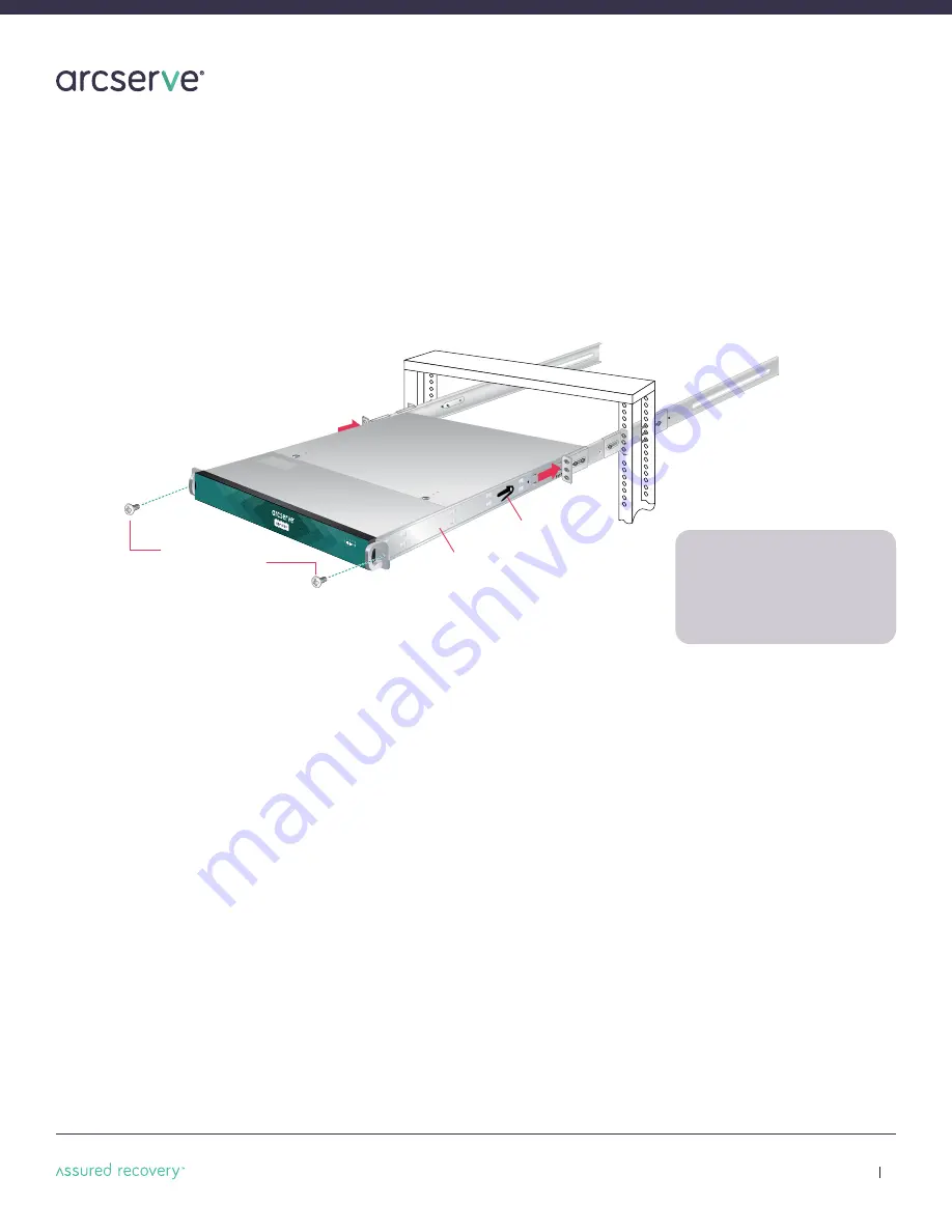
Two 10-32 x 3/4” 

Phillips flat-head screws

*

Fixed chassis rail

(attached prior to shipment)

Locking tab

10.   Installing the Appliance in the 2-Post Rack

n

Align the inner fixed chassis rails on the appliance with the fixed chassis rack rail assemblies previously installed 
in the rack.  

n

Carefully slide the appliance into the rack rails until you hear the locking tabs on the chassis rails click into place.  

n

Push the appliance all the way into the rack until it stops.

n

Secure the unit in the rack by inserting and tightening two 10-32 x 3/4” Phillips pan head screws, one on each side.

NOTE:

When removing the appliance

from your rack, you will need to press
down on the locking tab in order to 
release it from the rack. Carefully slide
it out supporting the unit on both sides
at all times.

Summary of Contents for UDP 8100

Page 1: ...HARDWARE INSTALLATION GUIDE Arcserve UDP 8100 and UDP 8200 Appliance Hardware Installation Guide ...

Page 2: ...Section 6B 4 Post Rack Installation with Quick Mount Rails square hole rack only 9 Section 7 Installing the Appliance in the 4 Post Rack 10 Section 8 Unpacking the 2 Post Rack Installation Hardware 11 Section 9 2 Post Rack Installation 12 Section 10 Installing the Appliance in the 2 Post Rack 13 Section 11 Rear Panel Connections 14 Section 12 Front Panel Operation 16 Section 13 Run Arcserve UDP Ap...

Page 3: ...ES 3 A NMB 3 A CE Mark Warning This is a Class A product In a domestic environment this product may cause radio interference in which case the user may be required to take adequate measures VCCI Warning This is a product of VCCI Class A Compliance Environmental Warning Perchlorate Material special handling may apply See www dtsc ca gov hazardouswaste perchlorate This notice is required by Californ...

Page 4: ...ceptacle on the power supply must be an IEC 320 sheet C13 type female connector n Plug the power cord s into a socket that is properly grounded before turning on the power CAUTION Required operating conditions for the appliance are n Temperature 10 to 35o C n Humidity non condensing 8 to 90 CAUTION CLASS 1 LASER PRODUCT APPAREIL À LASER DE CLASSE 1 DISPOSING OF BATTERY BACKUP UNITS IF APPLICABLE W...

Page 5: ...pment to avoid possible electrical shock n Use rubber mats specifically designed as electrical insulators when working with computer systems n The power supply or power cord must include a grounding plug and must be plugged into grounded outlets CAUTION Electric Static Discharge ESD can damage electronic components To prevent damage to your system board it is important to handle it very carefully ...

Page 6: ...KS MUST BE MOUNTED SECURELY Ensure that all leveling jacks or stabilizers are properly attached to the rack If installing multiple appliances in a rack make sure the overall loading for each branch circuit does not exceed the rated capacity Do not slide more than one appliance out from the rack at a time Extending more than one appliance at a time may result in the rack becoming unstable Install y...

Page 7: ...quare holes only n Two power cords n Two 10 32 x 3 4 Phillips pan head screws n One pair of adjustable quick mount rack rail assemblies requires no additional mounting hardware or tools Rack rail assembly outside view Rack rail assembly inside view Adjustable front rack rail assembly attaches to the front of the rack Adjustable rear rack rail assembly attaches to the rear of the rack Eight M5 x 12...

Page 8: ...ure the rack rail assemblies and screws are aligned in the rack not only in the front and back but are level in height on the left and right sides for proper alignment for appliance installation Step 1 Locate the two adjustable standard rack rail assemblies n Insert the tabs on the front section of the adjustable rack rail assembly through the openings in the rear sections of the assemblies n Chec...

Page 9: ...ck mount rail tabs side view Quick mount rail locking mechanism 4 post rack D C E A B NOTE Make sure the quick mount rail assemblies are aligned in the rack not only in the front and back but are level in height on the left and right sides for proper alignment for appliance installation Step 2 n Quick mount rail Installation in the square hole rack A Insert the quick mount rail tabs on the front o...

Page 10: ...ack rail assemblies previously installed in the rack n Carefully slide the appliance into the rack rails until you hear the locking tabs on the chassis rails click into place n Push the appliance all the way into the rack until it stops n Secure the unit in the rack by inserting and tightening two 10 32 x 3 4 Phillips pan head screws one on each side NOTE When removing the appliance from your rack...

Page 11: ...ir of 2 post rack mounting brackets with threaded holes n One pair of 2 post rack assemblies that attach directly to the rack 2 post rack rail assembly outside view 2 post rack rail assembly inside view Eight M5 x 12 Phillips flat head screws Two 10 32 x 3 4 Phillips pan head screws used to secure the appliance in the rack Twenty two M4 x 4 Phillips truss head screws NOTE Use the hardware supplied...

Page 12: ...set of short brackets to the long fixed bracket as shown using one M4 truss head screw on each bracket The three holes on the flap will face toward the front for later attachment to the 2 post rack Step 2 Attach the assembled brackets to the 2 post rack A Insert two M5 x 12 flat head screws through the short brackets into the 2 post rack in the front and back of the rack as shown and tighten Make ...

Page 13: ...sly installed in the rack n Carefully slide the appliance into the rack rails until you hear the locking tabs on the chassis rails click into place n Push the appliance all the way into the rack until it stops n Secure the unit in the rack by inserting and tightening two 10 32 x 3 4 Phillips pan head screws one on each side NOTE When removing the appliance from your rack you will need to press dow...

Page 14: ... 1 Power Supply Lock 1 K L M N O P Q R S T Power Good LED 2 Power Supply Lock 2 USB 2 0 Port 1 Black USB 2 0 Port 2 Black USB 3 0 Port 3 Blue USB 3 0 Port 4 Blue Network Data I O Port 1 Eth0 for Network 1 Network Data I O Port 2 Eth1 for Network 2 VGA Port Slot 2 Full Height PCIe Expansion Slot Slot 1 LSI 9361 4i RAID Controller Always present in Slot 1 Slot 3 Empty Quad Port NIC Empty Quad Port N...

Page 15: ... and Module 2 will be SOLID GREEN If the power is down both LEDs will BLINK GREEN Power Supply Status LED There is a single bi color Power Good LED on each power supply module to indicate power supply status The LED operation is defined in the table below CAUTION The power supply is hot swappable only when you have a server with redundant power supplies installed If you only have one power supply ...

Page 16: ...ally applied to the appliance the Arcserve UDP Appliance Wizard is launched Navigate through each page of the wizard For more information about the wizard see the Arcserve UDP Appliance User Guide arcserve com udp appliance userguide or view the video at arcserve com udp appliance wizard video Note After selecting the Operating System language a screen to enter Windows license may come up Skip to ...

Page 17: ...ta to deduplication non deduplication data stores on recovery point servers n Back up recovery points to tape n Create virtual standby machines from backup data n Replicate backup data to recovery point servers and remote recovery point servers n Restore backup data and perform Bare Metal Recovery BMR n Copy selected data backup files to a secondary backup location n Configure and manage Arcserve ...

Page 18: ...mation To the extent permitted by applicable law Arcserve provides this document as is without warranty of any kind including without limitation any implied warranties of merchantability fitness for a particular purpose or non infringement In no event will Arcserve be liable for any loss or damage direct or indirect from the use of this document including without limitation lost profits business i...

Reviews: