


Doc No. 740048
21
MODEL 96
TUBE TO TUBESHEET WELD HEAD
OPERATION MANUAL
13.0 Available Options
(Cont’d.)
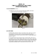
Nose rings
The Model 96 comes equipped with a universal nose ring. This nose ring
will accommodate all tube diameters up to 2.12” O.D. (53.8mm). For
critical applications, (such as when welding Titanium) or for applications
with very close tube spacing, allowing excessive shielding gas to be
diverted down adjacent tubes, specialized nose rings are available. These
nose rings are designed for specific tube sizes, tube spacing and tube
pattern, square or tri-pitch. Please contact the factory for
recommendations.
Extension Cables
The use of an extension cable does not eliminate the requirement for an
adapter. If an extension cable is used, it is connected between the power
supply and the adapter cable. See 3.0, Cable hook up..
For use with Power Supply models 205, 207A or 307.
Description
Part Number
25 ft. (7.7m) Extension Cable
13090806-01
50 ft. (15.4m) Extension Cable
13090806-02
75ft. (23.1m) Extension Cable
13090806-03
For use with Power Supply models 227 and 415.
50 ft. (15.4m) Extension Cable
13090808-01
75ft. (23.1m) Extension Cable
13090808-02


