


Doc No. 740048
11
MODEL 96
TUBE TO TUBESHEET WELD HEAD
OPERATION MANUAL
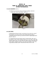
6.0 ELECTRODE GEOMETRY AND INSTALLATION
CAUTION
To prevent the possibility of electrical shock, the power
supply must be turned off or set to the “TEST” mode before
proceeding with electrode installation or removal.
6.1 The recommended electrode type is 2% Ceriated. (AWS Spec.
A5.12/A5.12M, Orange tip). This type of electrode provides superior
arc starting and longer life than 2% Thoriated electrodes. Other types
can also be used. Consult factory for recommendations.
6.2 The Model 96 comes with electrode holders for both 1/16” (1.6mm)
and 3/32” (2.4mm) diameter electrodes. A 0.040” (1.0mm) diameter
electrode holder is available.
6.3 The design of the Model 96 is such that a 1.000” (25.4mm) long
electrode, (properly installed in the electrode holder) will stick out the
same distance as the feet or tabs on the nose ring, which sits on the
surface of the tubesheet. Use this 1.000” (25.4mm) dimension to
calculate the appropriate electrode length for a flush tube application.
ELECTRODE LENGTH FORMULA:
1.000” (25.4m) minus the arc gap = electrode length.
6. 4 Electrode geometry and Arc Gap are primarily based on the tube
material and wall thickness. Although the Model 96 can
accommodate a wide variety of materials and preps (recessed, flush
or projected), the most common applications are stainless steel tube,
inserted flush with the tubesheet. The following two charts are based
on these types of applications.
Use this chart to establish a recommended electrode diameter.
Tube/Pipe
Wall thickness
Electrode
Diameter
0.015”–0.035” (.38 –.76mm)
0.040” or 1/16” (1.0 or 1.6mm)
0.036” – 0.083” (.91 – 2.1mm)
1/16” (1.6mm)
0.084” – 0.250” (2.1 – 6.3mm)
3/32” (2.3mm)
Fig. 7


