Arc Machines M96 Operation Manual Download Page 20

Doc No. 740048 

19


MODEL 96  

TUBE TO TUBESHEET WELD HEAD  

OPERATION MANUAL 


10.0 CLEANING AND MAINTENANCE 


CAUTION, DO NOT USE AIR PRESSURE  

ABOVE 20 PSI (139 Kp) (1.38 Bar)


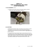
10.3   To clean the weld head, use a lint-free cloth and alcohol to wipe 

                     down all surfaces. 


11.0 STORAGE 


           11.1  Attach the dust cap to the electrical connector, and store the weld 
                    head in a clean, dust-free area.  


11.2  Do not store the weld head for more than 1 month without first  

                   draining the coolant from the weld head and hoses. Refer to chapter 
                   10.0 for coolant draining instructions.  


12.0 TUBE & TUBESHEET PREPARATION CONSIDERATIONS 


As with all welding applications, regardless of the welding process or the  

           material being welded, cleanliness of the materials being welded is of 
           upmost importance. Dirt, oil, paint, hydraulic fluid, oxidation, or any other 
           contaminant must be removed from both the tube and the tubesheet prior 
           to installing the tube into the tubesheet.  Cleaning the joint after the tube 
           has been installed will not be adequate, as contaminants trapped between 
           the tube and tubesheet cannot be removed, and will cause weld defects 
           and/or porosity. Additionally, contaminants can adhere to the electrode 
           and contaminate it. 


Fit up between the tube O.D. and the tubesheet hole I.D. is also very 

           important. If the tube is not in good contact with the tubesheet, weld  
           repeatability will suffer. Weld puddle characteristics will not be consistent  
           if the fit up is not consistent. In order to get repeatable thermal transfer 
           between the tube and the tubesheet, they must be in good contact with 
           each other. 


Summary of Contents for M96

Page 1: ...M96 WELD HEAD OPERATION MANUAL...

Page 2: ...ut notice WARNING The nature of the GTAW process creates some POTENTIAL HAZARDS In accordance with international safety regulations the EXCLAMATION SYMBOL indicates that this equipment is considered H...

Page 3: ...3 2 0 Unpacking 4 3 0 Cable hook up 5 4 0 Rotation speed Calibration 7 5 0 Mandrel installation 9 6 0 Electrode geometry installation 11 7 0 Gas chambers 15 8 0 Nose ring 16 9 0 Shielding gas 17 10 0...

Page 4: ...ectrode maintains a constant electrode to work arc gap distance as it rotates around the joint A gas chamber surrounds the arc and weld joint providing excellent shielding gas coverage This chamber ca...

Page 5: ...ap distance from electrode tip to tube is automatically set The electrode holder is mounted on a pivot arm which swings in or out to accommodate various tube diameters The integral 10ft 3 meter cable...

Page 6: ...on cables may also be used The use of an extension cable does not eliminate the requirement for an adapter If an extension cable is used it is connected between the power supply and the adapter After...

Page 7: ...ket head screw to allow the latch to open far enough to fully seat the two fittings Once the fittings are latched together lightly tighten this screw to prevent accidental disconnection See fig 2 Fig...

Page 8: ...ion See fig 6 Connect the air line to a clean dry air source of 90 120 PSI 6 2 8 3 Bar 4 0 ROTATION SPEED AUTO CALIBRATION Before welding the electrode rotation motor must be calibrated to the power s...

Page 9: ...eld head motor is manually calibrated by creating a weld program that should rotate the electrode 360 degrees ie 1 RPM for a total of 60 seconds 2 RPM for a total of 30 seconds 3 RPM for a total of 20...

Page 10: ...es slow it down by turning the potentiometer counter clockwise CCW Should the rotation be too slow stopping before it reaches its start location rotating less than 360 degrees turn the potentiometer c...

Page 11: ...he mandrel and slide the mandrel shaft into the center hole next to the electrode holder Slowly rotate the mandrel until the threaded end protrudes through the top of the weld head Reinstall the washe...

Page 12: ...25 4mm long electrode properly installed in the electrode holder will stick out the same distance as the feet or tabs on the nose ring which sits on the surface of the tubesheet Use this 1 000 25 4mm...

Page 13: ...0 020 0 030 0 50 76mm 0 010 0 020 25 50mm 0 036 0 083 91 2 1mm 0 030 0 050 76 1 3mm 0 020 0 030 50 76mm 0 084 0 250 2 1 6 3mm 0 050 0 070 1 3 1 8mm 0 030 0 040 76 1 0mm Fig 8 6 6 Loosen the socket hea...

Page 14: ...th the centerline of the electrode either in line with the tube O D or slightly outside the tube O D CAUTION POSITIONING THE ELECTRODE TOO CLOSE TO THE TUBE I D CAN CAUSE THE WELD PUDDLE TO ROLL INTO...

Page 15: ...EOMETRY AND INSTALLATION Cont d Fig 10 6 11 Once the electrode is positioned properly you can measure the distance across the electrode and the mandrel using a veneer caliper or other accurate measuri...

Page 16: ...schedule development as it allows the operator to see the weld puddle being formed is available as an optional accessory 7 1 To remove the chamber first release the two side latches and remove the no...

Page 17: ...tubesheet The nose ring that comes standard with the head is considered a generic nose ring and can be used for multiple applications Shown in Fig 12 For applications that require higher levels of pur...

Page 18: ...shielding gas used is Argon Gas mixtures of 95 Argon 5 hydrogen or 75 helium 25 argon are sometimes used to achieve deeper penetration Consult the factory for recommendations The Model 96 is designed...

Page 19: ...nternals Although you may not be storing the adapter and or extension cables leave them hooked up to the weld head when purging out the water 10 1 To drain the coolant from the weld head and cables us...

Page 20: ...welded cleanliness of the materials being welded is of upmost importance Dirt oil paint hydraulic fluid oxidation or any other contaminant must be removed from both the tube and the tubesheet prior t...

Page 21: ...04 0 68 0 74 I D 17 3 18 8mm 13961000 06 0 74 0 80 I D 18 8 20 3mm 13961000 09 0 80 0 84 I D 20 3 21 3mm 13961001 08 0 83 0 88 I D 21 1 22 4mm 13961001 02 0 88 0 93 I D 22 4 23 6mm 13961001 01 0 92 0...

Page 22: ...gs are designed for specific tube sizes tube spacing and tube pattern square or tri pitch Please contact the factory for recommendations Extension Cables The use of an extension cable does not elimina...

Reviews: