background image

Appendix

- 52 -

4.1 

I/O Map

Item
1

2

3

4
5
6
7
8
9
10
11
12
13
14
15
16
17
18
19
20
21
22
23
24
25
26
27
28
29
30

Address
0000h-0000Fh
0080h-009Fh
00C0h-00DFh
0020h, 0021h
00A0h, 00A1h
0040h-0043h
0044h-0047h
0060h-0064h
0070h-0073h
00F0h-00FFh
01F0h-01F7h
0274h-0277h
0279h , 0A79h
0295h , 0296h
02F8h-02FFh
0378h-037Ah
03B0h-03BFh
03C0h-03CFh
03D4h-03D9h
03F0h-03F7h
03F6h-03F6h
03F8h-03FFh
0400h-041F
04D0h-04D1h
0500h-053Fh
0800h-087Fh
0A00h-0A07h
0CF8h
0CFCh

Description
Direct memory access controller

Programmable interrupt Controller

System timer
Keyboard controller
System CMOS/real time clock
Math Co-Processor
Primary IDE
ISAPNP Read Data Port
ISAPnP Configuration
SuperIO Configuration Port
COM_2 (If use)
Parallel Port (If use)
MDA/MGA
EGA/VGA
CGA CRT 
Floppy Diskette
Primary IDE
COM_1 (If use)
South Bridge SMB 
IRQ Edge/level control ports
South Bridge GPIO
ACPI
PME
PCI Configuration address
PCI Configuration Data

Appendix

- 51 -

Appendix

4

Chapter 4

Summary of Contents for EmCORE-v7002

Page 1: ......

Page 2: ...EmCORE v7002 VIA Eden 3 5 Embedded Board User s Manual Version 1 0 2008 04...

Page 3: ...nnectors 10 Chapter 3 BIOS 19 3 1 BIOS Introduction 20 3 2 BIOS Setup 20 3 3 Standard CMOS Features 21 3 4 Advance BIOS Features 23 3 5 Advanced Chipset Features 26 3 6 Integrated Peripherals 30 3 7 P...

Page 4: ...Introduction 1 Introduction 1 Chapter 1...

Page 5: ...manufacturer 1 2 About this User s Manual This User s Manual is intended for experienced users and integrators with hardware knowledge of personal computers If you are not sure about any description i...

Page 6: ...repair it at no additional charge except as set forth in the following terms This warranty does not apply to products damaged by misuse modifications accident or disaster Vendor assumes no liability...

Page 7: ...v7002VL2 Standard Version Cable Kit 6911170020000P contains the followings Content 1 1 x AUDIO Cable 2 2 x USB Cable 3 1 x COM Flat Cable 4 1 x Serial ATACable 5 1 x IDE Cable 6 1 x Print Cable 7 1 x...

Page 8: ...1 9 Ordering Information EmCORE v7002VL2 3 5 Embeded Board With CPU LAN Audio VGA PC 104 SATA CBK 11 7002 00 NOTE BOX header version and all other specifications are available up on OEM request 1 10...

Page 9: ...24 bit Dual Channel LVDS 2x VIA VT6107 10 100 Base T Ethernet LAN support LAN boot WINBOUND W83697HG Phoenix Award BIOS version 6 0PG Support 4MB Flash ROM VIA VT1708A HD audio Supports MIC In Line I...

Page 10: ...1 11 Board Dimensions Introduction 7...

Page 11: ...Installation 2 Chapter 2 Installation 8...

Page 12: ...Installation 9 2 1 Board layout PC 104 IDE LPT LAN DIO1 CN3 J5 J6 JC2 USB3 4 JBAT SATA1 SATA2 FAN2 LVDS PWR1 PWR2 USB1 2 LAN KB MS J1 IR1 VGA JCOM1 COM1 COM2 AUDIO MPCI1 LLED1 USB5 6...

Page 13: ...lect AT ATX Power Select CF Card Master or Slave Select JBAT1 CMOS Jumper Settings Type onboard 3 pin header CMOS Setup JBAT1 Keep CMOS Clear CMOS JBAT1 1 2 ON 2 3 ON JP1 COM1 RS 232 422 485 Select Ty...

Page 14: ...D Power 5V 3 3V Power ATX AT JC2 1 2 2 3 J5 1 2 2 3 J5 AT ATX Power Select Type onboard 1 3 pin header J6 CF Card Master or Slave Select Type onboard 1 3 pin header Power Slave Master J6 1 2 2 3 JC2 D...

Page 15: ...onnector Serial Port 1 RS 422 485 Output Front Panel Switches and Indicators Parallel Port USB 3 4 Connector USB 5 6 Connector Power Connecter Power Connecter LVDS LCD Panel Connector Infrared IR Conn...

Page 16: ...DE RESET DATA7 DATA6 DATA5 DATA4 DATA3 DATA2 DATA1 DATA0 GND HD_DREQ HD_IOW HD_IOR HD_RDY HD_DACK IRQ ADDR1 ADDR0 HD_CS0 HD_ACT Pin 2 4 6 8 10 12 14 16 18 20 22 24 26 28 30 32 34 36 38 40 Description...

Page 17: ...1 Front Panel Type onboard 2 0pitch 10 pin 2 5 header Pin 1 3 5 7 9 Pin 1 2 3 4 Pin 1 3 5 7 9 Pin 1 3 5 7 9 Description DCD TX GND RTS RI Description RS485RTX RS485RTX RS422RX RS422RX Description RESE...

Page 18: ...tion 15 Pin 1 3 5 7 9 11 13 15 17 19 Pin 1 3 5 7 9 Pin 1 3 5 7 9 Description STB PDR0 PDR1 PDR2 PDR3 PDR4 PDR5 PDR6 PDR7 P_ACK Description 5V USBD3 USBD3 GND GND Description 5V USBD5 USBD5 GND GND Des...

Page 19: ...TX1O1 GND TX1O2 TX1O2 GND TX1O3 TX1O3 Description VPP TX2CLK TX2CLK GND TX2O0 TX2O0 GND TX2O1 TX2O1 GND TX2O2 TX2O2 GND TX2O3 TX2O3 Pin 2 4 6 8 10 12 14 16 18 20 22 24 26 28 30 LVDS1 PWR1 Power Connec...

Page 20: ...GND IRTX Description TX RX D2 D3 LAN_GND Description ACT ACT LILED LILED Description TX D2 RX D3 Key IR1 Infrared IR Connector Type onboard 2 54pitch 5 pin header LAN1 Ethernet Connector Type onboard...

Page 21: ...MIC1 GND LOUT_L Description LINR GND MIC2 GND LOUT_R Audio1 Audio Port Type onboard 2 5pin 2 0mm BOX header Installation 18 CN3 LVDS Panel Inverter Connector Type onboard 5 pin wafer Pin 1 2 3 4 5 Des...

Page 22: ...BIOS 19 BIOS 3 Chapter 3...

Page 23: ...el key immediately allows you to enter the Setup utility If you a little bit late press the Del key POST Power On Self Test will continue with its test routines thus preventing you from invoking the S...

Page 24: ...this option You will need to run the Standard CMOS option however if you change your system hardware configurations shch as onboard battery fails or the configuration stored in the CMOS memory was lo...

Page 25: ...Head Number of read write heads Precomp Write precompensation Landing Zone Landing zone Sector Number of sectors The Access Mode selections are as follows CHS HD 528MB LBA HD 528MB and supports Logic...

Page 26: ...for a keyboard error it will stop for all other errors All But Diskette The system boot will not be halted for a disk error it will stop for all other errors All But Disk Key The system boot will not...

Page 27: ...for IDE Hard Disk boot sector protection If this function is enabled and someone attempt to write data into this area BIOS will show a warning message on screen and alarm beep Setting Disabled default...

Page 28: ...ivate the NumLock function after you power up the system Setting On Default Off Typematic Rate Setting Key strokes repeat at a rate determined by the keyboard controller When enabled the typematic rat...

Page 29: ...1 4 default OS Select For DRAM 64MB Select the operating system that is running with greater than 64MB of RAM on the system Setting Non OS2 default OS2 Vedio BIOS shadow Enable copies Video BIOS to s...

Page 30: ...an be pulled This setting controls length of the wait Like CAS latency it s a delay before you get your data so while your system is faster at a lower setting it s also more stressful at that setting...

Page 31: ...automatic mode It allows you to determine when the Pentium 4 s Thermal Monitor should be activated in automatic mode after the system boots For example with the default value of 16 Minutes the BIOS a...

Page 32: ...memory is shared with system memory The default value is 8MB Boot Display This option let you select the display devices The options include VBIOS Default CRT LFP CRT LFP Setting CRT Panel Number Thi...

Page 33: ...BIOS 30 VIA OnChip IDE Device 3 6 Integrated Peripherals In this menu you can specify your settings for integrated peripherals...

Page 34: ...Disabled disable this function Setting Enabled default Disabled IDE Prefetch Mode If your system use ATA133 or SATA please select Enabled It can improve the perfoamnce of your system Setting Enabled...

Page 35: ...Setting Enabled default VIA OnChip PCI Device Onboard FDC Controller Select Enabled to activate USB Controller Select Disabled if you want to disable USB Controller Setting Enabled default Disabled O...

Page 36: ...Lo Lo Setting Hi Lo default IR Transmission Delay It allows you to select Enabled or Disabled to active or disable IR transmission Delay Setting Enabled default Disabled UR2 Duplex Mode Setting Full...

Page 37: ...her available modes Setting spp default EPP mode select You can use this feature to choose which version of EPP to use For better performance use EPP 1 9 But if you are facing connection issues try se...

Page 38: ...g Enabled default USB Operation Mode Enable or disable USB2 0 function Setting Enabled default USB Keyboard Mouse Function Enable or disable USB keyboard mouse function If select enabled or disabled y...

Page 39: ...ower Management Option It allows you to set the type of power saving management modes Setting User Define default Min Saving Max Saving HDD power down It allows you to select the type of HDD working m...

Page 40: ...V H SYNC BLank default DPSM support Blank Screen MODEM USE IRQ It allows you to set the IRQ NO for your system Setting 3 default Soft off by PWRBTN It defines the power off mode when using an ATX powe...

Page 41: ...ating system like Windows9x you can select Yes configure non boot devices by PNP OS if you select NO the BIOS would configure non boot devices Setting Disabled Default Enabled Reset Configuration Data...

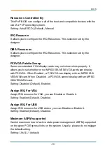
Page 42: ...designer DMA Resources It allows you to configure the IRQ Resources This selection set by the designer PCI VGA Palette Snoop Some non standard VGA display cards may not show colors properly It allows...

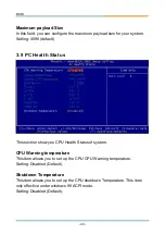
Page 43: ...alth Status This section show you CPU Health Status of system CPU Warning temperature This item allows you to set up the CPU CPU Warning temperature Setting Disabled Default Shutdown Temperature This...

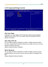
Page 44: ...led or Disabled to enable or disable automatic detect PCI clock please keep the default setting for your system if you do not know what the meaning of this item Setting Enabled Default Disabled Speed...

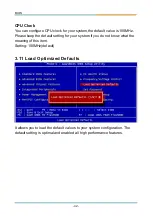
Page 45: ...lease keep the default setting for your system if you do not know what the meaning of this item Setting 100MHz default It allows you to load the default values to your system configuration The default...

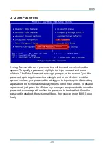
Page 46: ...characters in length and press Enter And the system confirms your password by asking you to type it again After setting a password the screen automatically returns to the main screen To disable a pass...

Page 47: ...y and save all the changes into the CMOS memory Typing N you will return to Setup utility 3 13 Save Exit Setup 3 14 Exit Without Saving Typing Y will quit the Setup utility without saving the modifica...

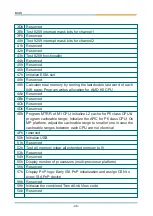
Page 48: ...erved Clear 8042 interface Initialize 8042 self test Test special keyboard controller for Winbond 977 series Super I O chips Enable keyboard interface Address 00000h 9FFFFh A0000h BFFFFh C0000h CFFFFh...

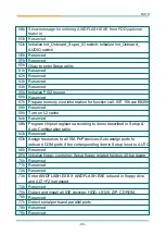
Page 49: ...F000 for ESCD DMI support Reserved Use walking 1 s algorithm to check out interface in CMOS circuitry Also set real time clock power status and then check for override Reserved Program chipset defaul...

Page 50: ...rate PCI busnumber assign memory I O resource search for a valid VGA device VGA BIOS and put it into C000 0 Reserved Reserved Reserved Initialize INT 09 buffer Reserved Program CPU internal MTRR P6 PI...

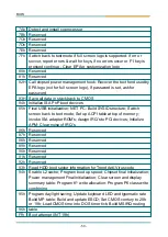
Page 51: ...rites allocation for AMD K5 CPU Reserved Reserved Reserved Reserved Program MTRR of M1 CPU initialize L2 cache for P6 class CPU program cacheable range Initialize the APIC for P6 class CPU On MP platf...

Page 52: ...mation for function call INT 15h ax E820h Reserved Turn on L2 cache Reserved Program chipset registers according to items described in Setup Auto Configuration table Reserved Assign resources to all I...

Page 53: ...oot devices Final USB initialization NET PC Build SYSID structure Switch screen back to text mode Set up ACPI table at top of memory Invoke ISA adapter ROM s Assign IRQ s to PCI devices Initialize APM...

Page 54: ...Appendix 51 Appendix 4 Chapter 4...

Page 55: ...h 03F6h 03F6h 03F8h 03FFh 0400h 041F 04D0h 04D1h 0500h 053Fh 0800h 087Fh 0A00h 0A07h 0CF8h 0CFCh Description Direct memory access controller Programmable interrupt Controller System timer Keyboard con...

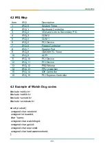
Page 56: ...Controller VGA and Link to Secondary PIC COM 2 COM 1 PCI Device Floppy Controller Parallel Port CMOS RTC Timer ACPI PCI Device PCI Device PS 2 Mouse FPU exception IDE Controller PCI Express Controller...

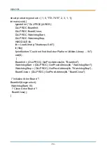
Page 57: ...brary libarborpu 0 dll if lib fprintf stderr Could not find the Arbor Platform Utilities Library N exit 0 BoardInit DLLPROC GetProcAddress lib BoardInit WatchdogStart DLLPROC GetProcAddress lib Watchd...

Reviews: