


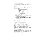

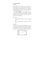


TRIG – Working with Triggers
Use TRIG to test various input signal conditions such
as voltage interruptions or frequency changes. When
these conditions match the defined triggering limits,
the 928A will record the start and stop times, and the
maximum, or minimum signal value during the event
(i.e. the date and time in which the trigger is active).
TRIG is very similar to PQ triggering as described
in the previous section. However, TRIG is more gen-
eral and flexible than PQ, and
does not
conform to
IEC 61000-4-30, paragraph 5.4.4.
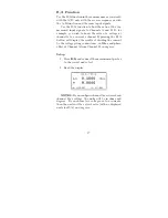
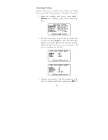
Viewing Triggers
Press
2nd
>
TRIG
to view the Trigger Events screen.
Press
or
to move through the record list.
In the screen shots above, REC 1 of 8 indicates
the date and time that TRIG #1 first became active
(i.e. triggered); note that no input signal levels are
recorded.
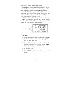
REC 2 of 8 shows the date and time TRIG #1
returned to normal limits, and became inactive (i.e.
“non-triggered”). Notice that REC 2 of 8 also indi-
cates a MAX (or MIN) value of the input signal during
the time while the trigger was previously active.
In this example, the Limit was set to 110.00, and
the lowest value recorded during this event was 109.689
volts at the date and time indicated.
54
Summary of Contents for 928A
Page 1: ...MODEL 928A USER S MANUAL Arbiter Systems Inc Paso Robles CA 93446 U S A ...
Page 6: ...vi ...
Page 12: ...xii ...
Page 14: ...xiv ...
Page 57: ...Channel B Combined Caution For current probe use see CT Probe Use on page 4 43 ...
Page 112: ...CT Cable Connector Figure 16 CT Cable Connector side view Figure 17 CT Connector End View 98 ...
Page 114: ...100 ...
Page 115: ...CE Mark Certification ...