background image

21

Waste pipe extension kit

!

If required, for larger baths, a 900mm waste pipe conversion kit is available from Aqualisa Customer
Service department. Please contact our Customer Service Department on 01959 560010.

1

Unscrew the clamping nut and remove the waste pipe from the waste assembly.

2

Remove the clamping nut and sealing washer from the waste pipe and set aside.

3

Carefully pull the waste pipe away from the outlet assembly. 

4

Reassemble the unit using the longer waste pipe by reversing the above procedure.

Shower valve user guide

Flow control - Single outlet valves

1. The lever in the 12 o’clock position indicates the valve is fully closed. When the lever 

is in the 9 o’clock position, the valve is fully open.

2. Turn the flow control lever anti-clockwise to turn the shower on. The more the lever is 

turned, the more water flow is delivered. 

3. Turn the flow control lever clockwise into the closed position after use.

Flow control - Divert valves

1. The lever in the 12 o’clock position indicates the valve is fully closed. When the lever is in the 9 o’clock 

position, the adjustable head outlet is fully open. When the lever is in the 3 o’clock position, the drencher 
head or bath fill is fully open. 

2. Turn the flow control lever clockwise or anti-clockwise to turn the desired shower outlet 

on. The more the lever is turned, the more water flow is delivered. 

3. Turn the flow control lever clockwise into the closed position after use.

N.B. Both shower heads/bath CANNOT be used simultaneously.

Summary of Contents for Dream DCV Series

Page 1: ...Dream Thermostatic Dual control mixer valve range Installation guide TM DCV ...

Page 2: ...essure systems p 6 Typical water systems p 7 System components p 9 Valve installation instructions p 11 Dream Dual Control Valve DCV p11 Shower head installation p 15 Adjustable height Harmony head p 15 Wall mount drencher head p 18 Bath overflow filler p 19 Waste pipe extension kit p 21 User guide p 21 Shower valve p 21 Adjustable height Harmony head p 22 Wall mount drencher head p 22 Cleaning ma...

Page 3: ... must be installed by a competent person in accordance with all relevant current Water Supply Regulations THE SHOWER MUST NOT BE USED WITH A HOT WATER SUPPLY TEMPERATURE OVER 65 C The Dream DCV range is designed for domestic use only Product specification Dream DCV products are suitable for all boosted gravity balanced high pressure and combination boiler systems Pressure range 1bar 5bar max stati...

Page 4: ...if left in contact will attack the working parts of the unit All soldering must be completed and the pipe work thoroughly flushed out in accordance with current Water Supply Regulations prior to connection of the product Filters To ensure ongoing optimum performance Dream DCV products are protected by inlet filter assemblies in the internal waterways Debris accumulation may result in reduced flow ...

Page 5: ...supply may be taken from the vent draw off pipe of the hot water cylinder at a point below the cylinder connection or alternatively from the underside of the horizontal draw off Rising pipe work must NOT be connected into the horizontal draw off from the cylinder or to any point in the vent draw off pipe above the cylinder connection CYLINDER TEMPERATURE IN EXCESS OF 65 C MAY RESULT IN POOR SHOWER...

Page 6: ...n from the nearest hot water draw off point Account must be taken of the pressure drops that will occur when other draw off points are used while the shower is in use Please refer to the typical system layout on page 7 When fitted to combination boiler systems Dream DCV shower valves have been specifically designed to give optimum temperature control and stability from fully modulating combination...

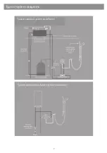
Page 7: ...7 Typical system diagrams Typical pumped system installation Typical combination boiler system installation ...

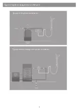
Page 8: ...Typical system diagrams continued Typical thermal storage unit system installation Typical UHW system installation 8 ...

Page 9: ...Components Dream DCV with adjustable head 9 Components Dream DCV with wall drencher head ...

Page 10: ...Components Dream DCV Divert with adjustable and wall drencher heads Components Dream DCV Divert with adjustable head and bath overflow filler 10 ...

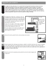
Page 11: ... necessary to first install a suitable sound fixing in the cavity area before fixing the valve A hole of 117mm wide x 135mm high is required to enable removal of the mortar guard and to allow for any future maintenance of the valve The valve needs to be mounted to the depth shown opposite The distance between the inch inlet pipe connections is 140mm 2 Remove the mortar guards from the valve assemb...

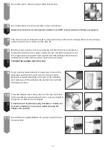
Page 12: ...d Once the infilling material has set carefully remove the mortar guards to expose the valve body THE MORTAR GUARDS MUST BE USED 9 Using a silicone based lubricant or liquid soap lubricate the wall plate seal within the round cut out of the wall plate Remove the double sided tape on the rear of the wall plate and carefully push the wall plate into position flush with the finished wall surface 10 S...

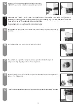
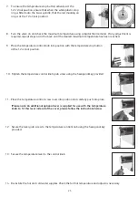
Page 13: ...mperature stop ring align at the 12 o clock position 16 Place the temperature control knob into position with the temperature stop button at the 12 o clock position 17 Tighten the temperature control knob grub screw using the hexagonal key provided The on off flow control Divert knobs can be fitted with or without the levers If not using the levers the hexagonal fixing points can be concealed usin...

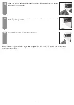
Page 14: ...into place 19 If fitting the lever secure the lever grub screw to the temperature control knob using the hexagonal key provided 20 Secure the temperature lever to the control knob Please refer to pages 15 to 20 for adjustable height head wall mount fixed head or bath overflow filler installation instructions 14 ...

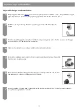
Page 15: ...length of 15 22mm using a rotary type cutter If a hacksaw is used the pipe end must be carefully de burred and chamfered 4 Clean and lubricate the pipe using a suitable silicone based lubricant 15 5 Remove the locking screw rotate the chrome outlet assembly and remove the outlet from the wall mounting plate 6 Place the wall outlet mounting plate onto the pipe assembly and mark and prepare the fixi...

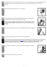
Page 16: ...lider levers depressed The top rail end bracket can be adjusted to suit existing screw holes in the finished wall by sliding the bracket up or down the rail to suit the required position 12 Carefully slide the gel hook onto the rail under the handset holder Current Water Supply regulations state that the handset should not be allowed to pass a point 25mm above the spill over level of the bath or s...

Page 17: ...7 Place the rail end caps into the rail ends and push firmly into position 18 Pass the hose through the gel hanger 19 Ensuring the hose washer is in the correct position secure the handset to the hose by pressing and holding the anti swivel locking button on the handset whilst securing the handset to the hose then place the handset into the handset holder 20 Ensuring the hose washer is in the corr...

Page 18: ...e is clean and free of dust and slide the fixing bush which incorporates the 15mm gripper ring down the projecting pipe flush with the wall spacer 4 Carefully remove the fixed head arm and drill and prepare the fixings using the fixings provided if suitable taking care to avoid pipework hidden in the wall 5 Ensuring the fixing bush is clean and free of dust fit the 15mm O ring against the end of t...

Page 19: ... or a tool with smooth jaws sufficiently to lock the head into position Bath overflow filler The bath overflow filler is suitable for baths up to a maximum thickness of 24mm 1 Carefully unscrew and remove the overflow filler outlet from the body assembly and set aside 2 Carefully unscrew and remove the bath waste clicker assembly from the waste body and set aside 3 Offer the bath waste into positi...

Page 20: ...sembly and bath wall 7 Ensuring the rubber washer is correctly aligned pass the overflow filler outlet through the bath and secure to the body assembly 5 Connect the bath waste to a suitable waste pipe 8 Remove the relevant inlet blanking plug and attach the flexible hose to the blended inlet connection 9 Connect the flexible hose to the blended supply pipe ensuring suitable non restrictive double...

Page 21: ...sed When the lever is in the 9 o clock position the valve is fully open 2 Turn the flow control lever anti clockwise to turn the shower on The more the lever is turned the more water flow is delivered 3 Turn the flow control lever clockwise into the closed position after use Flow control Divert valves 1 The lever in the 12 o clock position indicates the valve is fully closed When the lever is in t...

Page 22: ...ing up liquid DO NOT USE ABRASIVE CLEANERS To reduce the need for chemical descaling in hard water areas your shower head incorporates a clear flow system whereby any scale build up can be broken down by gently rubbing the flexible tips of the jets during use This procedure should be completed regularly as often as once a week in some hard water areas as scale build up can affect the spray pattern...

Page 23: ... at the 6 o clock position 3 Insert the hexagonal key into the temperature control knob and loosen the grub screw 4 With the shower running push the button in and rotate the control knob to the desired temperature Turn the shower off 5 Having rotated the temperature control knob to the desired position remove the temperature knob from the valve 6 Place the temperature knob back onto the valve with...

Page 24: ...e thermostatic cartridge by unscrewing anti clockwise from the valve using a 30mm socket or wrench 5 Screw the new cartridge into the body assembly and tighten using a 30mm socket or wrench 6 Adjust the temperature by turning the brass spindle clockwise for a cooler setting or anti clockwise for a warmer setting Please note The factory setting is set to 46 C This is marked with a red marking on th...

Page 25: ...sition with the temperature stop button at the 12 o clock position 10 Tighten the temperature control knob grub screw using the hexagonal key provided 11 Place the temperature control screw cover into position and carefully push into place Please note An additional optional lever is supplied for use with the temperature knob to fit this lever instead of the cover please follow the instructions bel...

Page 26: ...l air traps If the static water pressure exceeds 5 bar install a pressure reducing valve PRV in accordance with the installation guide Airlock in the hot water supply Water temperature swings regularly between hot and cold Flow rate is poor and water temperature is low Cold water pressure is too high Poor flow rate Twisted hose Debris in shower head Debris in filters Check for debris and clear as ...

Page 27: ...Notes 27 ...

Page 28: ...ail enquiries aqualisa co uk Republic of Ireland Sales enquiries 01 864 3363 Service enquiries 01 844 3212 Please note that calls may be recorded for training and quality purposes The company reserves the right to alter change or modify the product specifications without prior warning TM Trademark of Aqualisa Products Limited Part No 701142 Issue 01 Jun 14 ...

Page 29: ...r Showers Power Showers Smart Showers Shower Towers From Top Shower Brands Mira Showers Aqualisa Showers Triton Showers Gainsborough Showers Shower Pumps can upgrade your showering experience even more Stuart Turner Shower Pumps Salamander Shower Pumps Grundfos Shower Pumps ...

Reviews: