background image

17

M

AINTENANCE

DISCONNECT AND LOCK OUT POWER SOURCE

BEFORE SERVICING

WARNING

E

LECTRICAL

 S

CHEMATICS

115V


1

Ph  

60

Hz 

(USA)

Pump

Tgl Switch

mtr

115V

240V


1

Ph  

50

Hz 

 (Foreign)

Note: All green wires

go to ground

Denotes Line Connection
Denotes Wire Nut Termination

Electrical Schematic Code Designation

1.  Inspect Blade Assembly

       Clean the the exterior of the blades about 

       once a year or whenever a film of calcium or 

       mineral deposits is visible. While cleaning, 

       inspect for irregularities or hairline cracks and 

       replace as necessary.

2.   Flush Out Tank

       The tank should be rinsed regularly, especially 

       if using chemicals. Remove drain plug  


       (Part #481) and, using a garden hose, 

       thoroughly flush tank and pump of any 

       sediment.

3.   Main Motor

       The main motor is a permanently lubricated 

       motor, but occasionally applying some spray oil 

       to external rusty areas of the motor's body can 

       help extend the motor's life.

5.   Storage

       Protect your Aquafog from winter damage. 

       Expansion due to freezing can burst fittings, 

       solenoids and flowmeters. If storing unit in below 

       freezing temperatures, be sure all fluid is drained 

       from the unit. Damage due to freezing is not 

       covered under warranty. 

SPST

TGS

On

Black

White

Off

115 VAC

LINE

N

1, 3, 8

mtr

FAN

2, 4, 5

115V

Oscillator

mtr

115V

White

Blue

Pump

Tgl Switch

mtr

230V

DPST

TGS

On

Brown

Blue

Off

240 VAC

LINE

1

mtr

FAN

4, 5

240V

Oscillator

mtr

240V

Yellow

Blue

DPST

TGS

Off

On

2, 3, 8

N

www.JigglyGreenhouse.com  |  (800) 878-7829  |  [email protected]

Summary of Contents for GT 500-HS

Page 1: ...240V 50Hz Read Understand Retain for Future Reference GT 500 HS ATOMIZER USER S MANUAL AND OPERATING INSTRUCTIONS OPERATOR S MANUAL UL and CSA Electrical Components NOTICE GT www JigglyGreenhouse com...

Page 2: ...ting from misuse Safety Guidelines This manual contains very important information This information will help ensure SAFETY and PREVENT EQUIPMENT PROBLEMS Use these symbols to understand safety guidel...

Page 3: ...ited States National Electrical Codes NEC and Occupational Safety and Health Act OSHA 4 Only persons well acquainted with these rules of safe operation should be allowed to use the atomizer 5 Keep vis...

Page 4: ...ncentrate into the fresh water leading to the GT 500 HS Atomized Product Atomized Water or Chemical Solution Shut Off Valve Captured rainwater or pre mixed chemical solution located above GT 500 HS A...

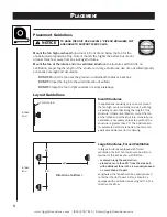
Page 5: ...the structure If there is ventilation mount the fan at the intake end of the structure Generally no oscillation is necessary unless the width of the structure is greater than 20 The best location for...

Page 6: ...part All fans should be equipped with oscillation sweeping 360 Large Structures Closed or Minimum Ventilation In closed structures with little to no ventilation propel fog the length of the structure...

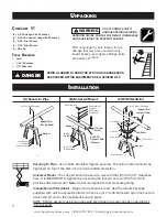
Page 7: ...AUSE INJURY OR PROPERTY DAMAGE WARNING Lock Washer Finish Nut Nylon Lock Nut Hanger Nylon Lock Nut Finish Nut Lock Washer Flat Washer 5 16 18 Bolt Package Hanger 2 1 4 20 Bolt Nylon Lock Nut Lock Wash...

Page 8: ...lot NOTE Use both sides of the M to access all four pivot angles Pivot Locking System Pivot Lock Motor s power cord Water line Wire tie Plug into a Control Panel or Plug into 60Hz electrical outlet UT...

Page 9: ...his cord is pre measured to the appropriate length DO NOT SHORTEN Remove the motor junction box cover Strip the ends of the oscillator power cord wires Using the wire nuts provided connect the oscilla...

Page 10: ...ze is smaller at lower outputs so it is better to operate the fan at a lower output for a longer period of time OPERATION BEFORE TESTING FAN MAKE SURE ALL OBJECTS ARE OUT OF THE ROTATION PATH OF THE F...

Page 11: ...may not be pointing properly into the reservoir behind the blade assembly The feed tube should be aimed slightly downward into the slot area between the motor shaft and the stainless steel plate rear...

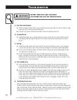
Page 12: ...nd remove mineral deposits and or calcium B If the vibration seems to be coming from the motor first check that the motor mounting hardware is securely tightened If hardware is secure remove the blade...

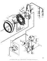
Page 13: ...y To Switch Box Lower Feed Tubing Sump Wall Internal Pump Parts 539 540 126 154 400 089 541 86 85 109 110 400 041 84 45 45 84 507 385 65 lg ID 65 lg ID 542 559 400 012 35 543 554 42 W 2 547 548 565 54...

Page 14: ...125 Oscillator s power supply port 154 58 32 514 500 658 42 660 57 58 Hanger Options U Bolts Hanger Bolt 395 116 518 514 13 500 USA USA 521 532 400 019 519 523 522 35 400 406 407 512 513 400 047 510...

Page 15: ...4 barb 1 406 Nylon rivet 6 407 Rivet washer 6 481 1 2 black hex plug 2 500 SST Hanger 1 502 Housing 1 506 Safety guard 1 507 115V Power cord for 60 50Hz models 1 510 Blade set screw 1 511 Blade tip se...

Page 16: ...8 bronze bearing 2 135 115 volt 60 Hz motor 1 136 220 240 volt 50 60 Hz motor 1 138 3 32 x 3 4 cotter pin SST 1 139 3 8 spacer 2 140 Thrust bearing 1 142 10 tooth brass gear 1 144 Upper gear stop 1 14...

Page 17: ...481 and using a garden hose thoroughly flush tank and pump of any sediment 3 Main Motor The main motor is a permanently lubricated motor but occasionally applying some spray oil to external rusty area...

Page 18: ...from direct or indirect misuse negligence accident lack of maintenance or unauthorized repairs or alterations which affect the machine s performance or reliability LIMITATIONS OF LIABILITY TO THE EXTE...

Reviews: