Aquadetox BioSaver- System / WRB 2000 Bio Manual Download Page 17

English

17

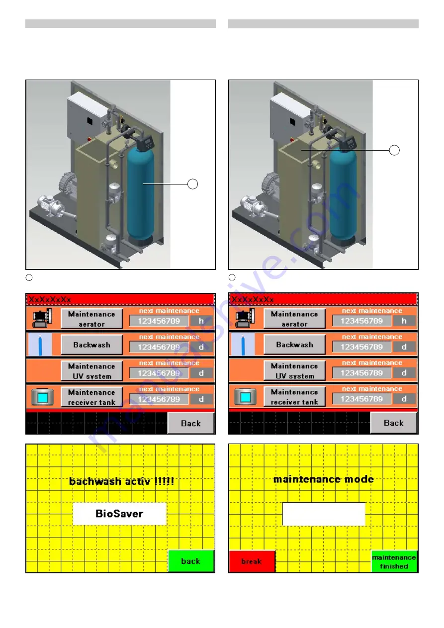
Post-treatment servicing

Note

No processed water for the washing process is provided during 
the flushing period. Cleaning may only be performed when no 
washing operations are being performed.

The display shows an information message when the post-treat-
ment stage needs to be flushed.

1

Backwashing

1. Touch the "Backwashing" button in the "Service" screen. 

The "Backwashing" screen opens and flushing is active.

2. Acknowledge completion of flushing (after approx 15 minutes) 

using the "Back" button.

Reservoir tank servicing

Note

The inlet is blocked during cleaning. Cleaning may only be per-
formed when no washing operations are being performed.

Deposits form in the processed water tank during operation. The 
display shows an information message when the reservoir tank 
needs to be cleaned.

1

Reservoir tank

1. Touch the "Reservoir tank" button in the "Service" screen. 

The "Service Mode" screen opens. 

The processed water tank is automatically drained, the immer-
sion pump in the biological stage is locked.

1

1

Summary of Contents for BioSaver- System / WRB 2000 Bio

Page 1: ...BioSaver System WRB Bio 59681090 11 19 001 Register your product www kaercher com welcome ...

Page 2: ...omponents such as batteries re chargeable batteries or oil which if handled or disposed of incorrectly can pose a potential danger to human health and the environment However these components are required for the correct operation of the device Devices marked by this symbol are not allowed to be disposed of together with the household rubbish On renewal of the filter material the used filter mater...

Page 3: ...hen power is suddenly restored after a power failure this can result in the system switching on uncontrollably Switch the system off in the case of a power failure DANGER Danger due to harmful substances Danger to health from contact with dust and microbiological con taminants Wear a suitable dust protection mask and gloves when replacing filters DANGER Danger due to harmful substances The recycli...

Page 4: ...ed for regeneration e g in the case of exces sive differential pressure Trigger this by pressing and holding the button for a longer period of time 5 The arrow button is used for decreasing a value Control head used from 12 2018 1 button The down arrow button is used for decreasing a value 2 button The up arrow button is used for increasing a value 3 CLOCK button This button is used for setting th...

Page 5: ... 2 1 Compressed air on site 2 Fresh water on site 3 Biological stage 2 4 Biological stage 1 5 Sludge trap 2 6 Sludge trap 1 7 Supply 8 Sludge trap 1 9 Sludge trap 2 10 Biological stage 1 11 Biological stage 2 12 Processed water 13 Aerator 14 Control cabinet ...

Page 6: ...d air on site 2 Fresh water on site 3 Biological stage 2 4 Biological stage 1 5 Pumping station 6 Sludge trap 7 Waste water supply 8 Sludge trap 9 Pumping station 10 Biological stage 1 11 Biological stage 2 12 Processed water 13 Aerator 14 Control cabinet ...

Page 7: ...nter the interior of the pipes when installing pipelines on site These materials can clog the fittings attached these pipelines during the first weeks of operation For this reason regularly check the func tion of the fresh water valve and pneumatic valve in the system during the first few weeks and clean the valves if necessary Note The waste water resulting from the cleaning of buildings walls fl...

Page 8: ...ply Note The control air supply to the control cabinet must be ensured at all times day and night A permanent supply of control air to the control cabinet is impor tant to ensure a correctly functioning system If the control air is provided via the company internal compressed air supply then ensure that this supply remains available at night on Sundays and public holidays Operation via the touch s...

Page 9: ...ange to the Variant 1 1 Pre treatment stage screen see Chapter Pre treatment sludge trap Variant 1 1 Pre treatment stage screen Pre treatment 2 button Change to the Variant 2 2 Pre treatment stages screen see Chapter Pre treatment sludge trap Variant 2 2 Pre treatment stages screen Biology 1 button Change to the Variant 1 1 biological stage screen see Chapter Biological stage Variant 1 1 biologica...

Page 10: ...re treatment 1 button displays the Variant 1 1 Pre treatment stage screen Pumping Station button Change to upstream system com ponents Pre treatment 2 button Change to downstream system components Pre treatment sludge trap Variant 2 2 Pre treatment stages screen Touching the Pre treatment 2 button displays the Variant 2 2 Pre treatment stages screen Pumping Station button Change to upstream system...

Page 11: ...n see Chapter Pre treatment sludge trap Variant 2 2 Pre treat ment stages screen Biology 2 button Change to the biological stage Variant 1 1 biological stage screen see Chapter Biological stage Variant 1 1 biological stage screen BioSaver button Change to the Post treatment screen see Chapter Post treatment screen Waste Water Pumping Station screen Touching the Pumping Station button displays the ...

Page 12: ...e screen see Chapter Fresh Water Valve screen Pressure Increase Pump button Change to the Aerator Pumps Valve fittings screen see Chapter The Aerator Pumps Valve fittings screen The Aerator Pumps Valve fittings screen ATTENTION Deactivated safety devices The system is manually switched from Manual mode to Automat ic mode Manual mode has the highest priority When manual mode is activated the safety...

Page 13: ...t manually ended the fresh water mode is automatically ended when the max filling level in the biological stage is reached Water Exchange button An increased salt concentration in the processed water can be reduced via the water exchange mode Touching the button activates the water exchange but ton is highlighted in green Touching the button again deacti vates the water exchange button is highligh...

Page 14: ...e system must continuously remain in opera tion also at night on public holidays and other standstill periods of the connected washing facility To keep the energy requirements as low as possible the auto matic control system is programmed to independently detect the volume of incoming waste water and dynamically reduce the run ning time of electrical units during low load phases such as at night o...

Page 15: ...the specifications of the standard installation situations Period Activity Person nel Daily Visual check of the control cabinet displays Operator Weekly Examination of the insertion sieve box in the sludge trap Checking of the aeration and circulation of the carrier material Operator Monthly Cleaning of the air intake filer of the aer ation unit Checking of the control air supply Checking of the f...

Page 16: ...he shaft and set it down on a suitable surface 2 Clean the insertion sieve box with a brush Biological stage servicing Note The aeration units in the stages must be checked for formation of coatings and deposits after 1 2 years The pre treatment sludge trap may need to be evacuated and disposed of This work can only be performed by Customer Service Contact your customer service partner responsible...

Page 17: ...hing is active 2 Acknowledge completion of flushing after approx 15 minutes using the Back button Reservoir tank servicing Note The inlet is blocked during cleaning Cleaning may only be per formed when no washing operations are being performed Deposits form in the processed water tank during operation The display shows an information message when the reservoir tank needs to be cleaned 1 Reservoir ...

Page 18: ... opens 2 Remove the wing nuts from the intake air filter protective hood 3 Remove the protective hood 4 Lift the intake air filter and clean with compressed air from the inside to the outside 5 Fit the protective hood and fasten with the wing nuts 6 Unscrew the air filter and clean with compressed air from the inside to the outside 7 Screw open the air filter Level sensor servicing The control sys...

Page 19: ...il layer disposed of by an approved disposal company Fault Rectification The processed water is cloudy despite no malfunc tion messages on the device 1 Check the cleaning agents for biological compatibility and correct dosage Contact the service agency responsible regarding this 2 Check that the fresh water injection has been set to 20 25 l fresh water per vehicle Contact the manufacturer of the w...

Page 20: ...tive 2011 65 EU These products meet the current requirements of the Ro HS directive for all 7 named materials Max 0 1 of weight in ho mogeneous material for lead mercury hexavalent chromium polybrominated biphenyl PBB polybrominated diphenyl ether PBDE deca BDE and max 0 01 of the weight for cadmium The system may not be operated until it has been ensured that the system has been installed accordi...

Reviews: